Materials pressure ratings, Dimensions – Cla-Val 100-20KO User Manual
Page 2
Specifications
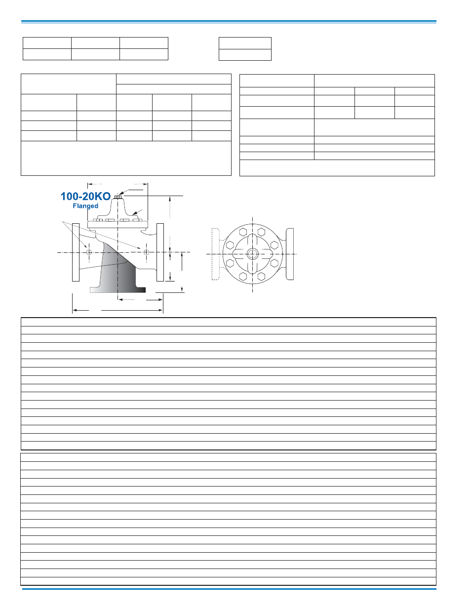
Model 100-20KO
Cla-Val Control Valves with KO ANTI-CAVITA-
TION Trim operate with maximum efficiency
when mounted in horizontal piping with the
main valve cover Up. We recommend isola-
tion valves be installed on inlet and outlet for
maintenance. Adequate space above and
around the valve for service personnel should
be considered essential. A regular maintenance
program should be established based on the
specific application data. However, we recom-
mend a thorough inspection be done at least
once a year. Consult factory for specific rec-
ommendations.
Pattern
Globe
Angle
Size
3" - 36"
4" - 6" - 8"
Component
Standard Material Combinations
Body & Cover
Ductile Iron
Cast Steel
Bronze
Available Sizes
3" - 36"
3" - 16"
3" 16"
Disc Retainer &
Diaphragm Washer
Cast Iron
Cast Steel
Bronze
Trim: Disc Guide,
Seat & Cover Bearing
Stainless Steel is Standard
Disc
Buna-N
®
Rubber
Diaphragm
Nylon Reinforced Buna-N
®
Rubber
Stem, Nut & Spring
Stainless Steel
For material options not listed consult factory.
Cla-Val manufactures valves in more than 50 different alloys.
Materials
Pressure Ratings
(Recommended Maximum Pressure - psi)
Valve Body & Cover
Pressure Class
Flanged
Grade
Material
ANSI
Standards*
150
Class
300
Class
ASTM A536
Ductile Iron
B16.42
250
400
ASTM A216-WCB
Cast Steel
B16.5
285
400
ASTM B62
Bronze
B16.24
225
400
Note:
* ANSI standards are for flange dimensions only.
Flanged valves are available faced but not drilled.
Valves for higher pressure are available; consult factory for details
Dimensions
EE
D
E
Inlet
DD
AA
F
A
C
(MAX)
K
J
H
Inlet
Outlet
FF
B
(Diameter)
Valve Size (Inches)
3
4
6
8
10
12
14
16
18
20
24
30
36
A 150 ANSI
10.25
13.88
17.75
21.38
26.00
30.00
34.25
35.00
42.12
48.00
48.00
63.25
65.00
AA 300 ANSI
11.00
14.50
18.62
22.38
27.38
31.50
35.75
36.62
43.63
49.62
49.75
63.75
67.00
B Dia.
6.62
9.12
11.50
15.75
20.00
23.62
27.47
28.00
35.44
35.44
35.44
53.19
56.00
C Max.
7.00
8.62
11.62
15.00
17.88
21.00
20.88
25.75
25.00
31.50
31.50
43.94
54.60
D 150 ANSI
—
6.94
8.88
10.69
—
—
—
—
—
21.06
—
—
—
DD 300 ANSI
—
7.25
9.38
11.19
—
—
—
—
—
—
—
—
—
E 150 ANSI
—
5.50
6.75
7.25
—
—
—
—
—
15.94
—
—
—
EE 300 ANSI
—
5.81
7.25
7.75
—
—
—
—
—
—
—
—
—
F 150 ANSI
3.75
4.50
5.50
6.75
8.00
9.50
11.00
11.75
15.88
14.56
17.00
19.88
25.50
FF 300 ANSI
4.12
5.00
6.25
7.50
8.75
10.25
—
12.75
15.88
16.06
19.00
22.00
27.50
H NPT Body Tapping
.375
.50
.75
.75
1
1
1
1
1
1
1
1
2
J NPT Cover Center Plug
.50
.50
.75
.75
1
1
1.25
1.25
2
2
2
2
2
K NPT Cover Tapping
.375
.50
.75
.75
1
1
1
1
1
1
1
1
2
Stem Travel
0.6
0.8
1.1
1.7
2.3
2.8
3.4
3.4
4.5
4.5
4.5
6.5
7.5
Approx. Ship Wt. Lbs.
45
85
195
330
625
900
1250
1380
2365
2551
2733
6500
9120
Valve Size (mm)
80
100
150
200
250
300
350
400
450
500
600
750
900
A 150 ANSI
260
353
451
543
660
762
870
889
1070
1219
1219
1607
1651
AA 300 ANSI
279
368
473
568
695
800
908
930
1108
1260
1263
1619
1702
B Dia.
168
232
292
400
508
600
698
711
900
900
900
1351
1422
C Max.
178
219
295
381
454
533
530
654
635
800
800
1116
1387
D 150 ANSI
—
176
226
272
—
—
—
—
—
—
—
—
—
DD 300 ANSI
—
184
238
284
—
—
—
—
—
—
—
—
—
E 150 ANSI
—
140
171
184
—
—
—
—
—
—
—
—
—
EE 300 ANSI
—
148
184
197
—
—
—
—
—
—
—
—
—
F 150 ANSI
95
114
140
171
203
241
279
298
403
370
432
505
648
FF 300 ANSI
105
127
159
191
222
260
—
324
403
408
483
559
699
H NPT Body Tapping
.375
.50
.75
.75
1
1
1
1
1
1
1
1
2
J NPT Cover Center Plug
.50
.50
.75
.75
1
1
1.25
1.25
2
2
2
2
2
K NPT Cover Tapping
.375
.50
.75
.75
1
1
1
1
1
1
1
1
2
Stem Travel
15
20
28
43
58
71
86
86
114
114
114
165
191
Approx. Ship Wt. Kgs.
20
39
89
150
284
409
568
627
681
1157
1249
2951
3876
Operating Temp. Range
Fluids
-40° to 180° F