Cla-Val 100-20KO User Manual
Page 3
For assistance in selecting appropriate valve options or valves manufactured with special design requirements, please contact our Regional Sales Office or Factory.
Model 100-20KO
Functional Data
K =
894d
4
C
2
v
L =
K
12 f
K Factor (Resistance Coefficient)
The Value of K is calculated from the formula:
(U.S. system units)
Equivalent Length of Pipe
Equivalent lengths of pipe (L) are determined from the formula:
(U.S. system units)
Fluid Velocity
Fluid velocity can be calculated from the following formula:
(U.S. system units)
d
V =
.4085 Q
2
d
C
V
Factor
Formulas for computing C Factor, Flow (Q) and Pressure Drop
V
( P):
C
V
=
Q
P
C
V
=
Q
P
C
V
=
Q
P
2
V
Where:
U.S. (gpm) @ 1 psi differential at 60 F water
(l/s) @ 1 bar (14.5 PSIG) differential
or
at 15 C water
inside pipe diameter of Schedule 40 Steel Pipe (inches)
friction factor for clean, new Schedule 40 pipe
(dimensionless) (from Cameron Hydraulic Data,
18th Edition, P 3-119)
Resistance Coefficient (calculated)
Equivalent Length of Pipe (feet)
Flow Rate in U.S. (gpm) or (l/s)
Fluid Velocity (feet per second) or (meters per second)
Pressure Drop in (psi) or (bar)
=
=
=
=
=
=
=
=
=
P
V
Q
L
K
f
d
C
Notes: On Operating Differential
*
The 100-20KO Series is the reduced inter-
nal port size version of the 100-01KO Series.
1. For atmospheric discharge, the
maximum inlet pressure cannot
exceed 150 psi.
2. For pressure differentials greater
than 300 psi the maximum flow
velocity should not exceed 18 ft/sec.
3. Flow velocities greater than 25 ft/sec
are not recommended.
4. Recommended minimum flow velocity
is 1 ft/sec.
5. Consult factory for conditions
exceeding these recommendations.
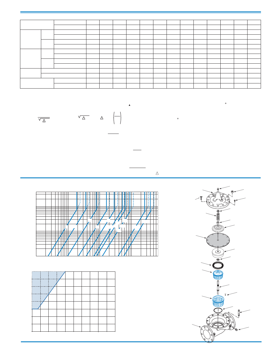
100G-20KO ANTI-CAVITATION VALVE CURVES
100
10
1000
10000
FLOW RATE (gpm)
10
100
PRESSURE DROP
(psi)
400
1
300
SOLID LINE IS FULL OPEN FLOW CURVES AT 18 FT/SEC FOR CONTINUOUS DUTY APPLICATIONS
DASHED LINE IS FULL OPEN FLOW CURVE AT 25 FT/SEC FOR INTERMITTENT DUTY APPLICATIONS
4"
6"
8"
10"
12"
14"
3"
30"
16"
24"
18"
20"
36"
SELECTION GUIDELINE FOR KO ANTI-CAVITATION VALVES
400
350
300
200
150
100
50
0
0
10
20
30
40
60
50
70
80
OUTLET PRESSURE (psi)
250
INLET
PRESSURE (psi)
Cavitation
Zone
90
100
COVER
PIPE PLUG
COVER BEARING
SPRING
STEM NUT
DIAPHRAGM WASHER
DISC RETAINER
BODY
*
SPACER WASHERS
PIPE PLUG
SEAT O-RING
STUD
10" and Larger
*
DIAPHRAGM
*
DISC
*
Repair Parts
PIPE PLUG
HEX NUT
10" and Larger
KO
DISC GUIDE
STEM
(Globe
Shown)
KO
SEAT
Seat Screw
10" and Larger
Cover Bolt
6" and Smaller
*
*
Valve Size
Inches
3
4
6
8
10
12
14
16
18
20
24
30
36
mm.
80
100
150
200
250
300
350
400
450
500
600
760
900
C V
Factor
Globe
Pattern
Gal./Min. (gpm.)
25
46
98
240
409
660
910
925
1175
1225
1271
3900
6200
Litres/Sec. (l/s.)
6.0
11.0
23.5
57.7
98
159
219
222
342
348
358
708
1490
Angle
Pattern
Gal./Min. (gpm.)
—
49
105
230
CF**
CF**
CF**
CF**
CF**
1200
CF**
—
—
Litres/Sec. (l/s.)
—
11.8
25.2
55
CF**
CF**
CF**
CF**
CF**
288
CF**
—
—
Equivalent
Length
of Pipe
Globe
Pattern
Feet (ft.)
1800
2191
4244
3404
3884
3190
3359
6472
6155
9752
22789
8373
8611
Meters (m.)
549
668
1294
1038
1184
972
1024
1973
1876
2973
6946
2552
2625
Angle
Pattern
Feet (ft.)
—
1931
3697
3257
CF**
CF**
CF**
CF**
CF**
CF**
CF**
—
—
Meters (m.)
—
589
1127
993
CF**
CF**
CF**
CF**
CF**
CF**
CF**
—
—
K
Factor
Globe Pattern
127
111
126
72
65
42
40
67
53
75
145
39
33
Angle Pattern
—
98
110
69
—
—
—
—
—
—
—
—
—
Liquid Displaced from Cover
Chamber When Valve
Opens
U.S. Gal.
.03
.08
.17
.53
1.26
2.5
4.0
4.0
9.6
9.6
9.6
29.0
42.0
Litres
.12
.30
.64
2.0
4.8
9.5
15.1
15.1
36.2
36.2
36.2
110
159