Cla-val, When ordering, please specify – Cla-Val 350-01/3650-01 User Manual
Page 8
CLA-VAL
Copyright Cla-Val 2011 Printed in USA Specifications subject to change without notice.
P.O. Box 1325
• Newport Beach, CA 92659-0325 • Phone: 949-722-4800 • Fax: 949-548-5441 • E-mail: [email protected] • Website cla-val.com
©
Input Voltage:
120/240 Vac +/- 10%, 50/60 Hz
Operating Current:
2 Amperes at 120 Vac
Process Variable:
Field Selectable between 4-20mA
transmitter (supplied by others)
or internal potentiometer
Loop Power Supply:
0-24 VDC
Retransmission:
Isolated non-powered 4-20mA
Input Signal Monitor:
If process variable is lost actuator
holds in present position, opens or
closes, field selectable
Set-Point:
Field selectable between local
and remote 4-20 mA, 0-5 Volt, 0-10 Volt
Manual Adjustment:
Non-rotating handwheel
Limit Switches:
Electronic-Full range adjustable
Terminations:
Terminal blocks accepting up to
#16 Awg solid or stranded wire
Operating Temperature: 0°F to 150 °F (-18 C to 65 C)
Environmental Rating:
Enclosure rated NEMA type 4
indoor/outdoor, corrosion resistant
aluminum
When Ordering, Please Specify
1. Catalog No. 350-01 or 3650-01
6. Trim Material
2. Valve Size
7. Adjustment Range
3. Pattern - Globe or Angle
8. Desired Options
4. Pressure Class
9. When Vertically
5. Threaded or Flanged
Installed
Adjustment Ranges
0 to 75
psi
20 to 200 psi
Temperature Range
Water: to 180°F
Materials
Standard Pilot System Materials
Pilot Control: Bronze ASTM B62
Trim: Stainless Steel Type 303
Rubber: Buna-N
®
Synthetic Rubber
Optional Pilot System Materials
Pilot Systems are available with optional Aluminum,
Stainless Steel or Monel materials.
Note: Available with remote sensing control.
Pilot System Specifications
Electronic Actuator - CRL-30 Pilot Control
Many factors should be considered in sizing pressure sustaining valves including inlet pressure, outlet
pressure and flow rates. For sizing questions or cavitation analysis, consult Cla-Val with system details.
E-350-01/3650-01 (R-7/2011)
We recommend providing adequate space around valve for maintenance work
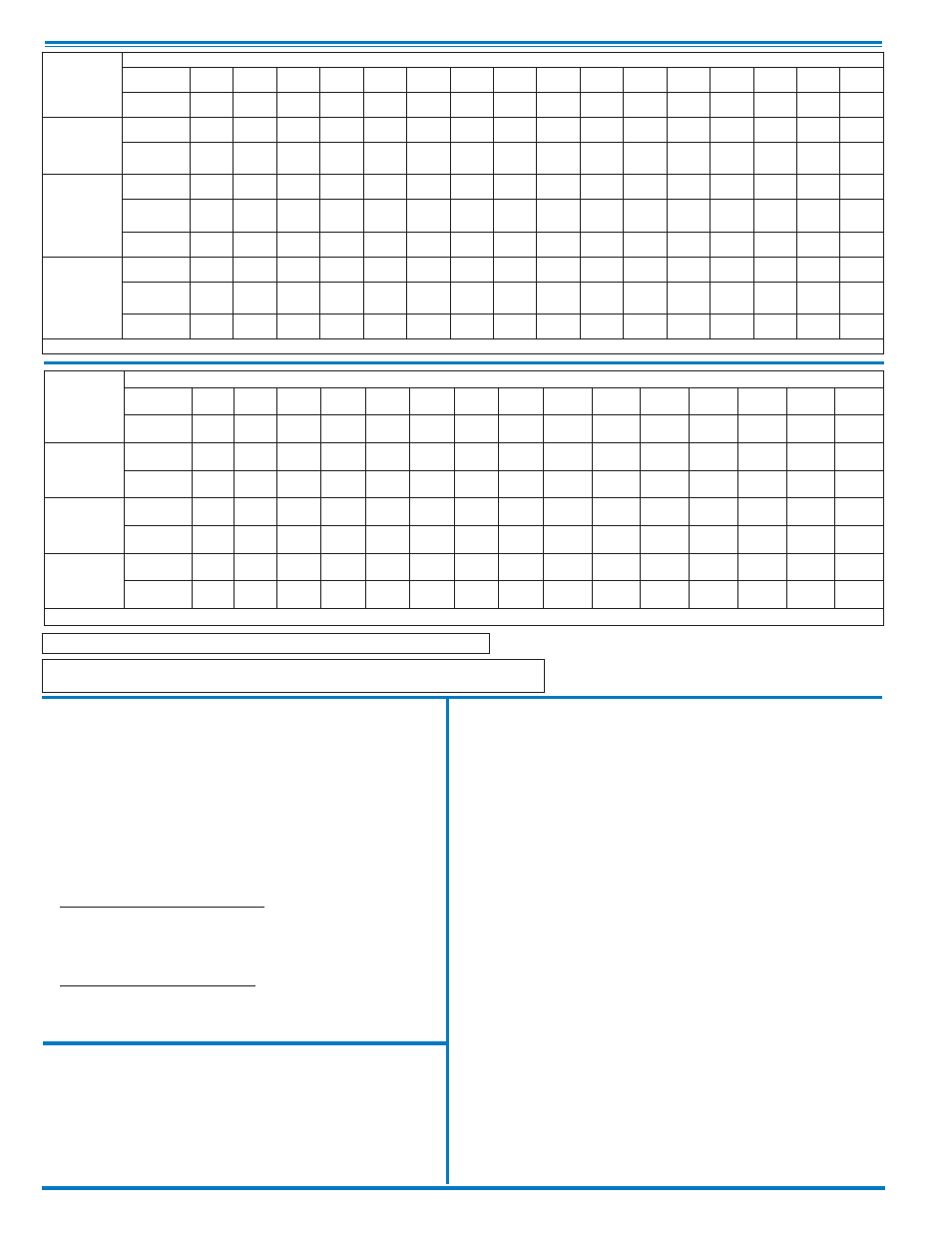
350-01
Valve
Selection
100-01 Pattern:
Globe (G), Angle (A),
End Connections:
Threaded (T), Grooved (GR), Flanged (F) Indicate Available Sizes
Inches
1
1
⁄
2
2
2
1
⁄
2
3
4
6
8
10
12
14
16
18
20
24
30
36
mm
40
50
65
80
100
150
200
250
300
350
400
450
500
600
750
900
Basic Valve
100-01
Pattern
G, A
G, A
G, A
G, A
G, A
G, A
G, A
G, A
G, A
G, A
G, A
G
G
G, A
G
G
End Detail
T, F,
Gr*
T, F,
Gr
T, F,
Gr*
T, F,
Gr
F,
Gr
F,
Gr*
F,
Gr*
F
F
F
F
F
F
F
F
F
Suggested
Flow
(gpm)
Maximum
125
210
300
460
800
1800
3100
4900
7000
8400
11000 14000 17000 25000 42000 50000
Maximum
Intermittent
160
260
370
580
990
2250
3900
6150
8720
10540 13700 17500 21700 31300 48000 62500
Minimum
1
1
2
2
4
10
15
35
50
70
95
120
150
275
450
650
Suggested
Flow
(Liters/Sec)
Maximum
8
13
19
29
50
113
195
309
442
530
694
883
1073
1577
2650
3150
Maximum
Intermittent
10
16
23
37
62
142
246
387
549
664
863
1104
1369
1972
3028
3940
Minimum
.03
.06
.09
0.13
0.25
0.63
0.95
2.2
3.2
4.4
6.0
7.6
9.5
17.4
28.4
41.0
100-01 Series is the full internal port Hytrol.
For Lower Flows Consult Factory
*
Globe Grooved Only
3650-01
Valve
Selection
100-20 Pattern:
Globe (G), Angle (A),
End Connections:
Flanged (F) Indicate Available Sizes
Inches
3
4
6
8
10
12
14
16
18
20
24
30
36
42
48
mm
80
100
150
200
250
300
350
400
450
500
600
750
900
1000
1200
Basic Valve
100-20
Pattern
G
G, A
G, A
G, A
G
G
G
G
G
G
G
G
G
G
G
End Detail
F
F
F
F
F
F
F
F
F
F
F
F
F
F
F
Suggested
Flow
(gpm)
Maximum
260
580
1025
2300
4100
6400
9230
9230
16500
16500
16500
28000
33500
33500
33500
Minimum
1
2
4
10
15
35
50
50
95
95
95
275
450
450
450
Suggested
Flow
(Liters/Sec)
Maximum
16
37
65
145
258
403
581
581
1040
1040
1040
1764
2115
2115
2115
Minimum
.06
.13
.25
.63
.95
2.2
3.2
3.2
6.0
6.0
6.0
17.4
28.4
41.0
41.0
100-20 Series is the reduced internal port size version of the 100-01 Series.
For Lower Flows Consult Factory