Cla-val, 01ko, When ordering, please specify – Cla-Val 90-01KO User Manual
Page 8: Pilot system specifications
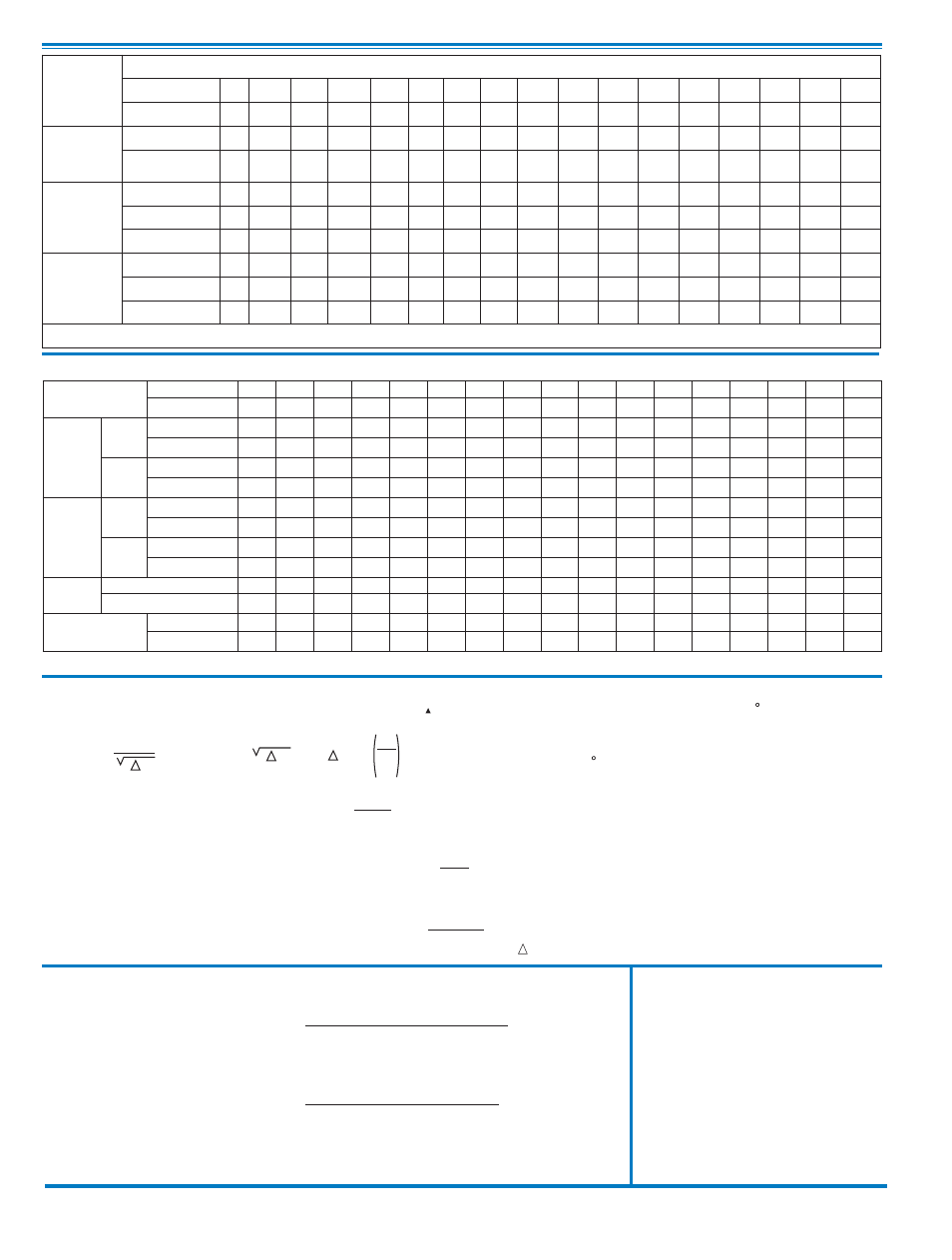
Functional Data
CLA-VAL
Copyright Cla-Val 2011 Printed in USA Specifications subject to change without notice.
P.O. Box 1325
• Newport Beach, CA 92659-0325 • Phone: 949-722-4800 • Fax: 949-548-5441 • E-mail: [email protected] • Website cla-val.com
©
E-90-01KO (R-7/2011)
For assistance in selecting appropriate valve options or valves manufactured with special design requirements, please contact our Regional Sales Office or Factory.
K =
894d
4
C
2
v
L =
K
12 f
K Factor (Resistance Coefficient)
The Value of K is calculated from the formula:
(U.S. system units)
Equivalent Length of Pipe
Equivalent lengths of pipe (L) are determined from the formula:
(U.S. system units)
Fluid Velocity
Fluid velocity can be calculated from the following formula:
(U.S. system units)
d
V =
.4085 Q
2
d
C
V
Factor
Formulas for computing C Factor, Flow (Q) and Pressure Drop
V
( P):
C
V
=
Q
P
C
V
=
Q
P
C
V
=
Q
P
2
V
Where:
U.S. (gpm) @ 1 psi differential at 60 F water
(l/s) @ 1 bar (14.5 PSIG) differential
or
at 15 C water
inside pipe diameter of Schedule 40 Steel Pipe (inches)
friction factor for clean, new Schedule 40 pipe
(dimensionless) (from Cameron Hydraulic Data,
18th Edition, P 3-119)
Resistance Coefficient (calculated)
Equivalent Length of Pipe (feet)
Flow Rate in U.S. (gpm) or (l/s)
Fluid Velocity (feet per second) or (meters per second)
Pressure Drop in (psi) or (bar)
=
=
=
=
=
=
=
=
=
P
V
Q
L
K
f
d
C
Valve Size
Inches
1
1
⁄
4
1
1
⁄
2
2
2
1
⁄
2
3
4
6
8
10
12
14
16
18
20
24
30
36
mm.
32
40
50
65
80
100
150
200
250
300
350
400
450
500
600
750
900
C
V
Factor
Globe
Pattern
Gal./Min. (gpm.)
14
14
25
37
52
90
218
362
660
810
1100 1200 1550 1950 3900 6100 9150
Litres/Sec. (l/s.)
3.4
3.4
6.0
8.9
12.5
21.6
52
87
159
194
264
288
360
469
938
1466 2199
Angle
Pattern
Gal./Min. (gpm.)
15
15
26
39
55
95
232
388
479
790
1075 1175
—
—
—
—
—
Litres/Sec. (l/s.)
3.6
3.6
6.2
9.4
13.2
22.8
56
93
115
190
258
282
—
—
—
—
—
Equivalent
Length of
Pipe
Globe
Pattern
Feet (ft.)
196
196
237
277
416
572
858
1315 2444 2118 1937 3022 3537 4199 4532 3897 3954
Meters (m.)
60
60
72
84
127
174
262
401
745
646
590
921
1078 1280 1381 1188 1205
Angle
Pattern
Feet (ft.)
171
171
219
250
372
514
757
1145 2133 2226 2021 3152
—
—
—
—
—
Meters (m.)
52
52
67
76
113
157
231
349
650
678
616
961
—
—
—
—
—
K Factor
Globe Pattern
30.6
30.6
26.1
24.3
29.3
29.0
25.5
27.7
41.0
27.7
22.8
31.4
30.2
29.5
28.9
17.6
15.1
Angle Pattern
26.7
26.7
24.1
21.8
26.2
26.0
22.5
24.1
35.8
29.1
23.8
32.8
—
—
—
—
—
Liquid Displaced from
Cover Chamber When
Valve Opens
U.S. Gal.
0.2
0.2
.03
.04
.08
.17
.53
1.26
2.5
4.0
6.5
9.6
11
12
29
65
90
Litres
0.8
0.8
.12
.16
.30
.64
2.0
4.8
9.5
15.1
25.6
36.2
41.6
45.4
110
246
340
Adjustment Ranges
2
to
30 psi
15 to
75
psi
20
to
105 psi
30
to 300 psi*
*Supplied unless otherwise specified
Other ranges available, please consult factory
Temperature Range
Water: to 180°F
Materials
Standard Pilot System Materials
Pilot Control: Bronze ASTM B62
Trim: Stainless Steel Type 303
Rubber: Buna-N
®
Synthetic Rubber
Optional Pilot System Materials
Pilot Systems are available with optional
Aluminum, Stainless Steel or Monel materials.
Note: Available with remote sensing control.
When Ordering, Please Specify
1. Catalog No. 90-01KO
2. Valve Size
3. Pattern - Globe or Angle
4. Pressure Class
5. Threaded, Flanged or Grooved End
6. Trim Material
7. Adjustment Range
8. Desired Options
9. When Vertically Installed
Pilot System Specifications
90-01KO
Valve
Selection
100-01KO Pattern:
Globe (G), Angle (A),
End Connections:
Threaded (T), Grooved (GR), Flanged (F) Indicate Available Sizes
Inches
1
1
⁄
4
1
1
⁄
2
2
2
1
⁄
2
3
4
6
8
10
12
14
16
18
20
24
30
36
mm
32
40
50
65
80
100
150
200
250
300
350
400
450
500
600
750
900
Basic Valve
100-01KO
Pattern
G, A G, A G, A G, A G, A G, A G, A G, A G, A G, A G, A G, A
G
G
G, A
G
G
End Detail
T
T, F,
Gr*
T, F,
Gr
T, F,
Gr*
T, F,
Gr
F,
Gr
F,
Gr*
F,
Gr*
F
F
F
F
F
F
F
F
F
Suggested
Flow
(gpm)
Max. Continuous
84
115
190
270
410
710
1620 2810 4420
6280
7590
9920 12550 14900 22600 37700 52450
Max. Intermittent
120
160
260
370
580
990
2250 3900 6150
8720 10540 13700 17500 21700 31300 48000 62500
Min. Continuous
10
10
15
20
30
50
115
200
300
400
500
650
560
1073
1577
2650
3150
Suggested
Flow
(Liters/Sec)
Max. Continuous
5.3
7.3
12
17
26
45
102
177
279
397
479
694
792
940
1427
2379
3309
Max. Intermittent
7.6
10
16
23
37
62
142
246
387
549
664
863
1104
1369
1972
3028
3940
Min. Continuous
.6
.6
.9
1.3
1.9
3.2
7.2
13
19
25
32
41
41
57
110
132
180
100-01KO Series is the full internal port Hytrol.
For Lower Flows Consult Factory
*
Globe Grooved Only