Cla-val – Cla-Val 133-11/633-11 User Manual
Page 4
CLA-VAL
Copyright Cla-Val 2013 Printed in USA Specifications subject to change without notice.
P.O. Box 1325
• Newport Beach, CA 92659-0325 • Phone: 949-722-4800 • Fax: 949-548-5441 • E-mail: [email protected] • Website cla-val.com
©
E-133-11/633-11 (R-2/2013)
Temperature Range
Water: to 180°F
Rubber Parts:
Buna-N
®
Rubber
Synthetic
Solenoid Control
Body:
Brass ASTM B283
Enclosure: NEMA Type 1,2,3,3S,4,4
X
general
purpose watertight
NEMA Type 6,6P,7,9 watertight
explosion proof available at
additional cost.
*
For specifications on other 133/633 Series Valves,
please consult factory. The 133-11/633-11 is shown.
Voltage:
110 -50Hz AC
24, 120, 240, 480 - 60Hz AC
6, 12, 24, 120, 240 - DC
Max. operating pressure differential:
200 psi
Coil:
Insulation Molded Class
F
Watts AC
6
AC Volt Amps Inrush
30
AC Volt Amps Holding
16
Watts DC
10.6
Manual operator available at additional cost.
Pilot System Specifications*
When Ordering, Please Specify
1. Catalog No. 133-11 or No. 633-11
2. Valve Size
3. Pattern - Globe or Angle
4. Pressure Class
5. Threaded or Flanged
6. Trim Material
7. Orifice Bore
8. Desired Options
9. When Vertically Installed
Note:
Orifice plate assembly (X52D-1) 1
1
⁄
2
" thick and must
be installed minimum 5 pipe diameters downstream
of valve with minimum of 3 pipe diameters of
straight pipe downstream of orifice plate assembly.
Orifice plate assembly sensing connections should
be located to the side of the pipeline. To increase
measurement accuracy, recommended minimum is
10 pipe diameters upstream and 5 pipe diameters
downstream of the orifice plate assembly.
We recommend providing adequate space around valve for maintenance work
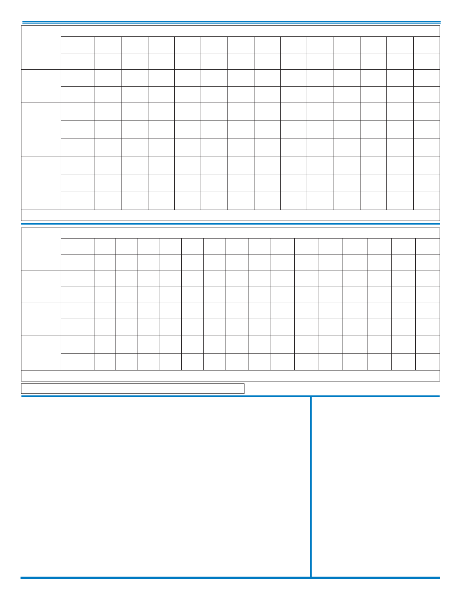
133-11
Valve
Selection
100-01 Pattern:
Globe (G), Angle (A),
End Connections:
Threaded (T), Grooved (GR), Flanged (F) Indicate Available Sizes
Inches
3
4
6
8
10
12
14
16
18
20
24
30
36
mm
80
100
150
200
250
300
350
400
450
500
600
750
900
Basic Valve
100-01
Pattern
G, A
G, A
G, A
G, A
G, A
G, A
G, A
G, A
G
G
G, A
G
G
End Detail
T, F,
Gr
F,
Gr
F,
Gr*
F,
Gr*
F
F
F
F
F
F
F
F
F
Suggested
Flow
(gpm)
Maximum
460
800
1800
3100
4900
7000
8400
11000
14000
17000
25000
42000
50000
Maximum
Intermittent
580
990
2250
3900
6150
8720
10540
13700
17500
21700
31300
48000
62500
Minimum
2
4
10
15
35
50
70
95
120
150
275
450
650
Suggested
Flow
(Liters/Sec)
Maximum
29
50
113
195
309
442
530
694
883
1073
1577
2650
3150
Maximum
Intermittent
37
62
142
246
387
549
664
863
1104
1369
1972
3028
3940
Minimum
0.13
0.25
0.63
0.95
2.2
3.2
4.4
6.0
7.6
9.5
17.4
28.4
41.0
100-01 Series is the full internal port Hytrol.
For Lower Flows Consult Factory
*
Globe Grooved Only
633-11
Valve
Selection
100-20 Pattern:
Globe (G), Angle (A),
End Connections:
Flanged (F) Indicate Available Sizes
Inches
3
4
6
8
10
12
14
16
18
20
24
30
36
42
48
mm
80
100
150
200
250
300
350
400
450
500
600
750
900
1000
1200
Basic Valve
100-20
Pattern
G
G, A
G, A
G, A
G
G
G
G
G
G
G
G
G
G
G
End Detail
F
F
F
F
F
F
F
F
F
F
F
F
F
F
F
Suggested
Flow
(gpm)
Maximum
260
580
1025
2300
4100
6400
9230
9230
16500
16500
16500
28000
33500
33500
33500
Minimum
1
2
4
10
15
35
50
50
95
95
95
275
450
450
450
Suggested
Flow
(Liters/Sec)
Maximum
16
37
65
145
258
403
581
581
1040
1040
1040
1764
2115
2115
2115
Minimum
.06
.13
.25
.63
.95
2.2
3.2
3.2
6.0
6.0
6.0
17.4
28.4
41.0
41.0
100-20 Series is the reduced internal port size version of the 100-01 Series.
For Lower Flows Consult Factory