Cla-val – Cla-Val PC-1 User Manual
Page 4
for remote signal alarm of Failure To Develop Pressure.
K.) Terminals 18 and 19 are dry-contact type (N.O. rated: 1
Amp, 120 VAC) for connection to customer supplied circuit
for remote signal alarm of Loss Of Pressure.
L.) Terminals 20 and 21 are dry-contact type (N.O. rated: 1
Amp, 120 VAC) for connection to customer supplied circuit
for remote signal alarm of Valve Fail To Open.
M.)Terminals 22 and 23 are dry-contact type (N.O. rated: 1
Amp, 120 VAC) for connection to customer supplied circuit
for remote signal alarm of Valve Re-Closed during start
sequence.
N.) Terminals 24 and 25 have 120/60 AC power (N.O. up to 1
Amp - fused at F4) present when an alarm condition exists
and are for connection to customer supplied circuit for
remote signal alarm of Loss Of Power Restart Delay.
Typically, this would activate a relay for the alarm signal.
O.)Terminals 26 and 27 are dry-contact type (N.O. rated: 1
Amp, 120 VAC) for connection to customer supplied circuit
for remote signaling of the H-O-A switch being in the "Auto"
position. When the H-O-A switch is in the "Auto" position,
no power contact is "made" at these terminals.
P.) Terminals 28 and 29 are dry-contact type (24 volt DC, 10
Milliamp) for connection to customer supplied no-voltage
circuit to provide an "Anti-Plugging" input signal from the
pump (if so equipped) when the pump is coasting or spinning
in reverse. When these contacts are "made" from the pump,
a start sequence will not be allowed.
OPERATION CHECK OUT AND BENCH TEST
The following steps are for a PC-1 operation check out and bench
test. This test is for newer PC-1 panels built since January 1998
and that have on the lid face the following: a) Lamp-test/Reset
switch, b) H-O-A switch mounted to the left-of-center, c) lid has red
and blue color markings on white background, and d) inside the
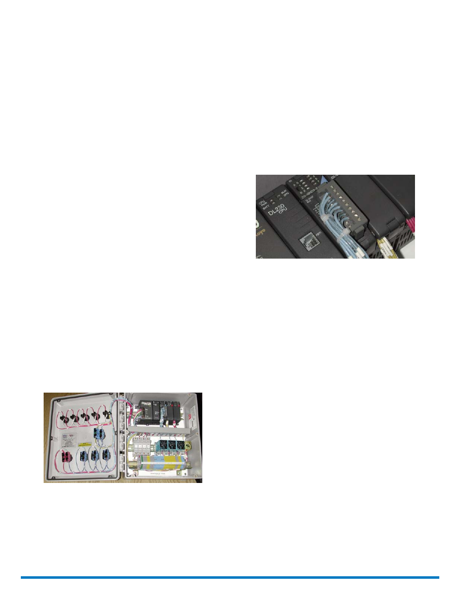
PC-1 is an Automation-Direct brand modular-style PLC. PC-1’s
built before September 1996 used an Omron brand dedicated PLC
for internal control sequencing and does not follow this sequence
exactly.
Preparation:
A.) PC-1 hooked up to 120/60 VAC at terminals 1, 2, and Ground.
B.) No other inputs or outputs hooked up to the PC-1.
C.) Set Time Delay Relays TR1, TR2, and TR3 to zero time.
D.) H-O-A switch is in OFF position.
The following steps occur when power is applied:
1. On the lid, the white panel light (Power) goes on.
2. On the inside, the CPU module PWR and RUN green
indicators go on.
3. On the inside, the Input module red indicators A0, A7, and
B0 go on (use A/B selector switch to switch between A and
B series).
4. On the inside, the TR1 relay ON and OUT lights are on.
NOTE: If the white panel light does not go on, then the E-STOP
switch is depressed. Lifting the E-STOP switch will turn on white
panel light. The switch must "click" into place.
NEXT, turn the H-O-A switch from OFF to HAND, then push green
(Start) button. Watch for:
1. On the lid, the blue panel light (Pressure) goes on and about
three seconds later the green panel light (Valve Open) goes on.
2. On the inside, the Input module red indicator lights A3, A5,
A6, A7, B0, and B4 go on.
3. On the inside, the TR1, TR2, and TR3 relay ON and OUT
lights go on.
4. On the inside, the CR1 relay red indicator light goes on.
NOTE:
a) To verify that panel lamps are functionary properly, depress
and hold Lamp Test/RESET button. All five panel lights go
on for about three to five seconds and then go off.
b) If the amber panel light (Restart/Delay) flashes, then
depress the Lamp Test/RESET button for at least 30
seconds to reset the PC-1. You may hear some relay
clicking from inside the PC-1, this is normal. If AC power
to terminals 1, 2, and ground are removed for 30 seconds,
the PC-1 will also reset.
c) If the Lamp Test/RESET button is released before complete
reset, then when the HOA switch is turned from OFF to
HAND (or if it was already in HAND), AND then Start button
is pushed, the amber panel light will flash. A complete 30
second reset will turn off flashing amber panel light.
d) If the Lamp Test/RESET button is released before complete
reset and the amber panel is flashing, THEN when the E-
STOP switch is depressed and then lifted, the red panel
light goes on and the amber panel light will continue to flash.
A complete 30 second reset will turn off red panel light and
flashing amber panel light.
CLA-VAL
Copyright Cla-Val 2008 Printed in USA Specifications subject to change without notice.
P.O. Box 1325
• Newport Beach, CA 92659-0325 • Phone: 949-722-4800 • Fax: 949-548-5441 • E-mail: [email protected] • Website cla-val.com
©
N-PC-1 (R-1/08)