Cla-Val PC-1 User Manual
Page 2
open for deep well pumps). The valve limit switch is adjusted to
actuate when the valve is in closed position (or open for deep well
pumps). For valve switch adjustment procedure, see Cla-Val
Model X105L Valve Limit Switch Assembly data sheet in technical
manual for pump control valve.
DISCHARGE PRESSURE SWITCH
In order to use the pressure-related functions of the PC-1, an
optional customer supplied pressure switch must be installed
between pump discharge and control valve inlet. The Normally
Open contacts of the pressure switch are used (contacts close
when pressure setting is reached or exceeded). If a pressure
switch is not used, a factory supplied jumper must be installed
across terminals 9 and 10. Remove jumper when installing pres-
sure switch.
ANTI-PLUGGING PUMP SWITCH
Some pumps have built-in contacts to indicate pump motor shaft is
rotating (forward or backward) when no electric power is applied.
These Anti-Plugging Pump Contacts are used for signaling to the
PC-1 that pump is rotating. These contacts are closed when pump
is rotating and keep PC-1 from initiating a start sequence and
potentially causing pump damage.
LAMP TEST/ALARM RESET SWITCH
Momentarily pushing of this switch will test all indicator lamps
when power is on (they will all light while the switch is depressed).
A 5 to 10 second push of this switch will reset (or acknowledge)
any alarm light signal and all lights will go off (white light remains
on). If the alarm condition is not corrected after acknowledgment
by this switch, the alarm will again trip.
EMERGENCY STOP SWITCH
This push-pull, snap-action switch will remove all power to PC-1
outputs when pushed IN. The internal PLC remains powered.
When switch is pulled OUT the PC-1 will operate normally. The
switch must "click" into place. Activating this switch requires a
heavy manual force.
OUTPUTS
The PC-1 control outputs are:
1. Valve Pilot Solenoid Output Control Circuit (120/60 VAC
powered)
2. Valve E-Stop Solenoid Output Control Circuit (120/60 VAC
powered)
3. Pump Motor Start Command Circuit (non-powered but
fused)
4. Failure to Develop Pressure Remote Alarm Output Circuit
(non-powered)
5. Loss of Pressure Remote Alarm Output Circuit (non-
powered)
6. Valve Failed to Open Remote Alarm Output Circuit (non-
powered)
7. Valve Reclosed Remote Alarm Output Circuit (non-powered)
8. Loss of Power Restart Delay Alarm Output Circuit (120/60
VAC powered)
9. H-O-A Switch in Auto Position Remote Contacts Output
Circuit (non-powered)
TIMERS
The PC-1 is supplied with three field adjustable timers. These
timers provide easy-to-set adjustment of pump start sequence
steps. In case of mechanical trouble with pump, control valve, or
system, these timers keep PC-1 from completing a start sequence.
Timer T1 is LOSS OF POWER AUTOMATIC RESTART DELAY
TIMER. After a loss of power, an automatic pump restart will occur
upon the expiration of timer T1 provided that:
a. The H-O-A switch is in Automatic
b. A signal is present to start the pump remotely (terminal 12 and 13)
c. The valve indicates closed (via valve position switch at
terminals 10 and 11)
NOTE: Automatic restart is disabled by removing jumper from ter-
minals 14 and 15.
Timer T2 is PRESSURE DELAY SEQUENCE TIMER (PDST).
Upon initiation of a pump start command, the PDST is energized.
The pilot valve solenoid is energized upon expiration of the PDST.
In booster pump applications, this time maybe used to allow the
pump to develop discharge pressure before opening the pump
control valve. In deep well pump applications, the time may be
used to flush the system prior to closing the valve and placing the
pump on the system.
Timer T3
is VALVE SEQUENCE TIMER (VST).
The VST is energized when the pilot valve solenoid is energized.
If the valve fails to open (close for deep well pumps) prior to the
VST expiring, an automatic shutdown will occur.
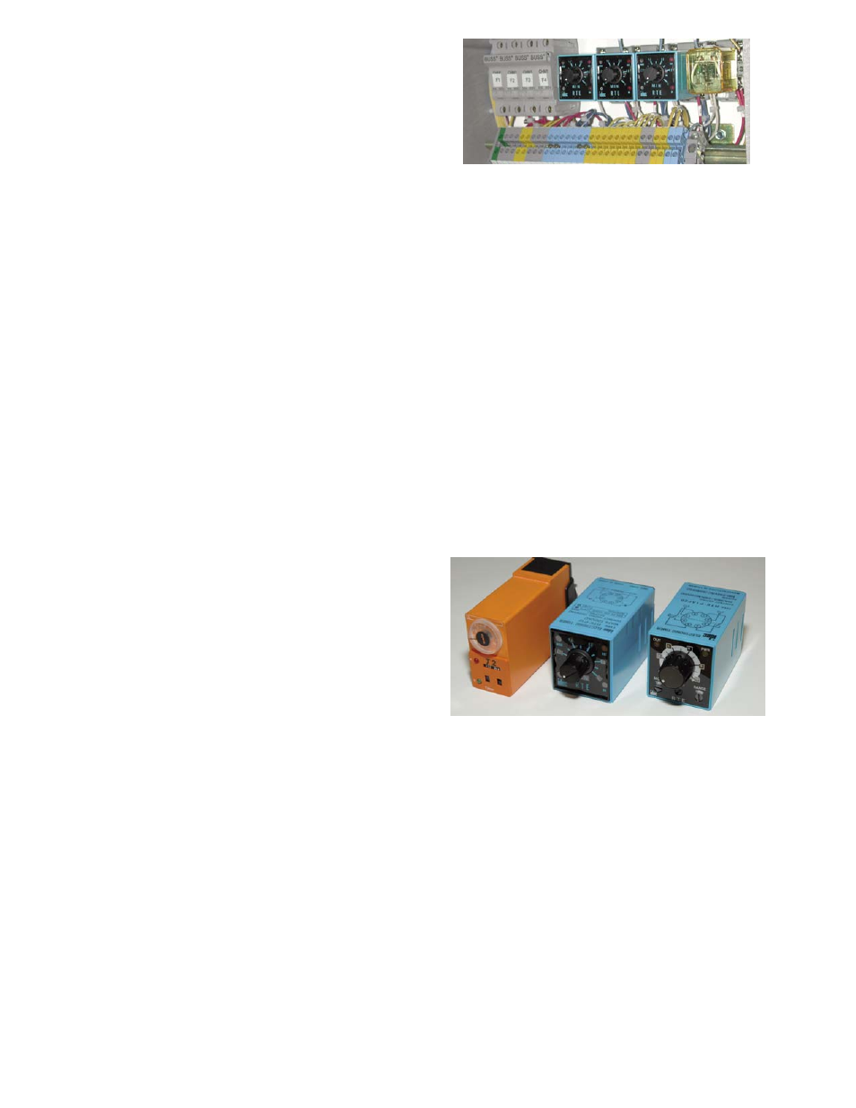
SETTING TIMERS T1, T2, and T3
The Cla-Val PC-1 Pump Control Panel is supplied with three field
adjustable timers (time delay relays) marked T1, T2, and T3. After
setting desired time delay, during the pump start sequence power
is applied to relay coil and control contacts remain open and power
(PWR) light is on. After preset time has elapsed, relay shifts to
close contacts and out (OUT) light is on. Reset occurs when
power is removed by PLC inside PC-1.
There have been three different styles of time delay relays used for
T1, T2, and T3. Each style of relay has different setting instruc-
tions depending on date of PC-1 manufacture.
A. Prior to January 1998, the timers were an orange cube-style
(Syrelec Model OAR2U delay on make) with an adjustable range
of 0.1 sec to 10 hours and used these instructions for setting time
delay.
1. Select Hours, Minutes, or Seconds with the Time Base
Selection Switch on the lower right-hand front. Use a small
screwdriver (4 mm maximum width) to move switch up or
down and view desired setting in window above switch.
Make sure switch clicks or snaps into place.