Cla-Val PC-1 User Manual
Page 3
2. Select desired multiplier (x0.1 or x1) by moving Scale
Selection Switch located to the left of the time base switch.
Make sure switch clicks or snaps into place.
3. Rotate Dial (for 0 to 10 units) to desired time delay setting
within the Time Base range and Scale multiplier selected.
B. Between January 1998 and January 2004, the timers were a
blue cube-style (IDEC Model RTE-P12) and used these instruc-
tions for setting time delay.
1. Select desired maximum time range using only Time Range
Group 2 in following table. Table is also on bottom side of
relay. M = minutes, H = hours
2. Remove thin plastic dial faceplate. Use a small screwdriver
(4 mm maximum width) under lip at bottom center to
carefully pry faceplate off relay top. Do not remove knob.
3. Digital Switch is located on lower left corner of relay top face.
Adjust digital switch up or down with a small screwdriver until
desired time range number is displayed in window.
4. Mode of Operation switch is located on upper left corner of
relay top face. This switch must be kept in the right-hand
position for "Delay on Make" operation.
5. Rotate inner portion of plastic dial faceplate until desired
time range and units show in faceplate windows. You may
have to turn plastic dial over to find desired range and to
match dial color. Refer to above chart. Reinstall plastic dial
on top of relay by inserting top edge tabs into top slots.
Bend the dial faceplate slightly as it is placed over knob and
insert the bottom edge into the bottom slot of the timer. As
dial faceplate "snaps" into place at the top, make sure that
inner dial remains in place.
6. Use center knob to set amount of time delay desired within
the range selected.
C. Starting in January 2004, the timers were changed to a blue
cube-style (IDEC Model RTE-P1AF20) and use these instructions
for setting time delay.
1. Select desired time range using following table. Set Time
Range Selector and Dial Selector at bottom of relay face to
corresponding positions for desired time range. Use a small
screwdriver (4 mm maximum width) to turn selectors. Make
sure switch clicks or snaps into place. DO NOT FORCE
BEYOND END POSITION.
2. Mode of Operation switch is located on lower left corner of
relay top face. This switch must be kept in the ”A” mode
position for "Delay on Make" operation.
3. Use center knob to set amount of time delay desired within
the range selected.
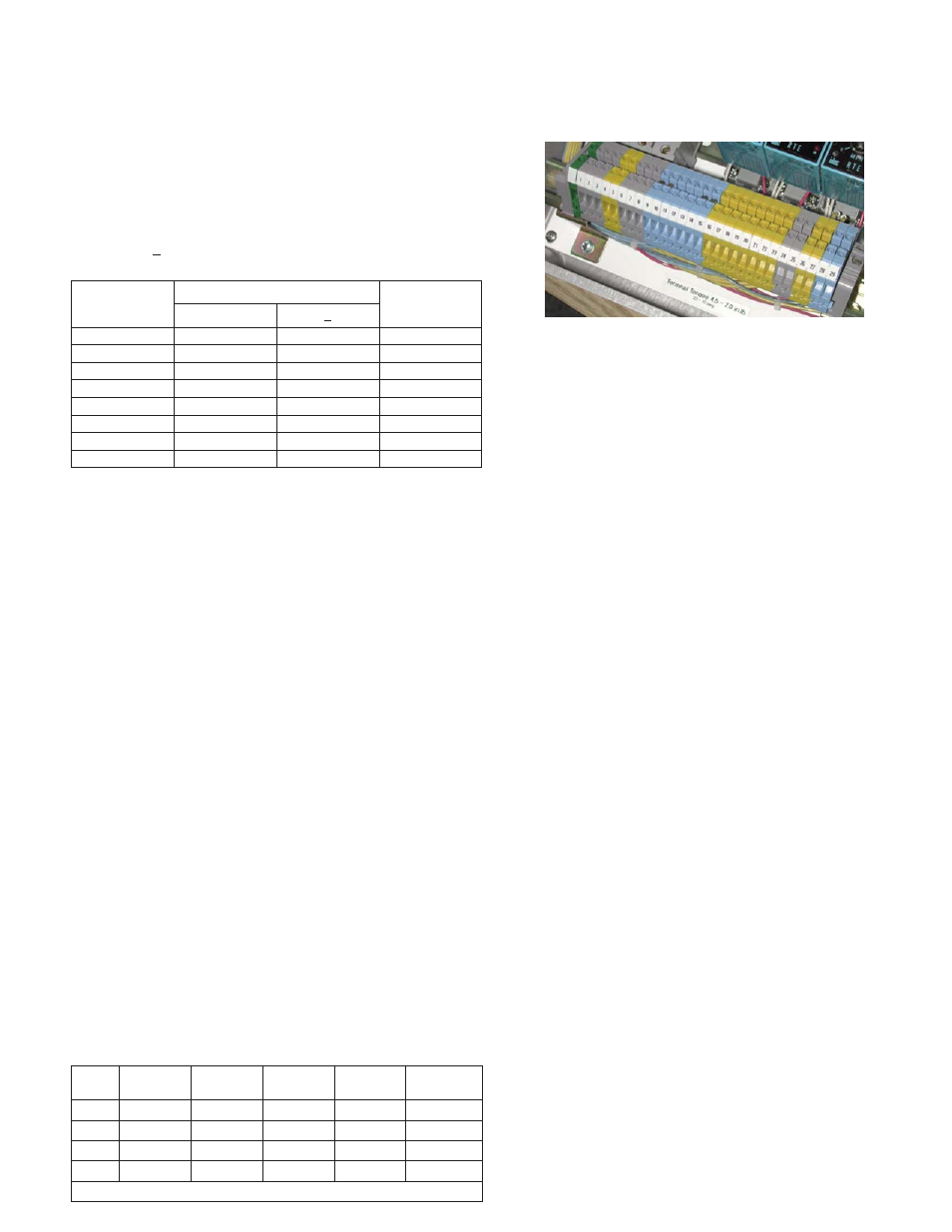
FIELD WIRING HOOKUP TERMINALS
The following describes the input and output terminals of PC-1
panels built since January 1996. Refer to Field Wiring Hookup dia-
gram Cla-Val drawing 204377 included with this manual.
A.) Terminals 1, 2 and Ground are for connecting 120 Volt 60Hz
AC (5 Amp fused) power (customer supplied). This is for
power to the PC-1 itself. Terminal 3 is NOT used.
B.) Terminals 4 and 5 are dry-contacts (N.O. rated: 120 VAC, 10
Amp - fused at F1) for connection to customer supplied
pump motor starter circuit.
C.) Terminals 6 and 7 have 120 Volt AC power (up to 1 Amp -
fused at F2) present (the PC-1 will energize these when
needed) and are to be connected to the Emergency Closing
Solenoid on the control valve (if present).
D.) Terminals 7 and 8 have 120 Volt AC power (up to 1 Amp -
fused at F3) present (the PC-1 will energize these when
needed) and are to be connected to the Pilot Valve Solenoid
on the control valve.
E.) Terminals 9 and 10 are dry-contact type (24 volt DC, 10
Milliamp) for connection to customer supplied no-voltage
circuit to Pressure Switch (N. O. contact and Common
contact) located between pump output and valve inlet (if
present).
F.) Terminals 10 and 11 are dry-contact type (24 volt DC, 10
Milliamp) for connection to customer supplied no-voltage
circuit to Cla-Val Model X105L Valve Limit Switch (N. O.
contact and Common contact) mounted on the valve.
G.)Terminals 12 and 13 are dry-contact type (24 volt DC, 10
Milliamp) for connection to customer supplied no-voltage
circuit to provide Remote/Automatic Start with the PC-1.
When these contacts are "made" and with the H-O-A switch
in Automatic, the PC-1 will initiate a start of the pump and
continue to allow the pump to run until this contact is broken.
H.) Terminals 14 and 15 are for allowing automatic Loss of
Power Restart with the jumper installed (standard). PC-1
will automatically initiate a pump start after power is
restored. If the jumper is not present, the PC-1 will not
initiate a pump start when power is restored after a loss of
power. A manual reset with the Lamp Test/Reset switch
(30-sec. minimum) will be needed to restart the pump after
power is restored.
J.) Terminals 16 and 17 are dry-contact type (N.O. rated: 1
Amp, 120 VAC) for connection to customer supplied circuit
Digital Switch
Position
Time Range Group
Dial Color
1
2
0, (or 8)
1 S
1 M
Blue
1, (or 9)
3 S
3 M
Violet
2
6 S
6 M
Violet
3
10 S
10 M
Blue
4
60 S
60 M
Violet
5
30 S
30 M
Violet
6
5 M
5 H
Blue
7
10 M
10 H
Blue
Range
0 - 1
scale
0 - 3
scale
0 - 10
scale
0 - 30
scale
0 - 60
scale
s
0.1 s-1 s
0.1 s-3 s
0.2 s-10 s 0.6 s-30 s 1.2 s-60 s
min
1.2 s-1 m 3.6 s-3 m 12 s-10 m 36 s-30 m 1.2 m-60 m
h
1.2 m-1 h 3.6 m-3 h 12 m-10 h 36 m-30 h 1.2 h-60 h
10 h
12 m-10 h 36 m-30 h 2 h-100 h 6 h-300 h 12 h-600 h
s = seconds, m = minutes, h = hours