Figure 1 – Cla-Val 60-11/660-11 Technical Manual User Manual
Page 6
Inspection Of Parts
Returning to the valve body in the line. the seat should now b
inspected for damage. If the seat requires removal use the fol-
lowing tools. Seats in valve sizes1/2" and 3/4" can be remove
with a hex socket wrench. Seats in valve sizes 1" through 6"
should be removed with accessory X-109 Seat Removing Too
available from the factory. Seats in valve sizes 8" through 16"
may be removed with a screw driver. If upon removal of the
screws the seat cannot be lifted out, it will be necessary to use
a hard rubber mallet and tap the seat loose.
Any buildup of mineral or scale should be cleaned from the
valve body at this time. Inspection of the cover and power unit
body surfaces that contact the diaphragm is important. Clean
and smooth. with wet or dry emery paper. any roughness that
could damage the diaphragm. Inspect and recondition the sur-
face on the upper and lower diaphragm washers The perimeter
if the diaphragm washers is the most likely area to cause
diaphragm wear if the surface is not smooth. Take extra care to
make this a smooth finish
Inspect the power unit body bearing insert O-ring that is in con-
tact with the stem If it is worn. nicked or cut. replace it.
The cover bearing should also be checked for excessive wear,
using the upper end of the stem to check for excessive lateral
movement. A special tool for each size valve is available from
the factory to remove the cover bearing. Cover bearing replace-
ment is seldom necessary.
Inspect the diaphragm for cracks or chafing. Replace the
diaphragm if damaged
Inspect the disc and replace if the surface is damaged or worn
If a new disc is not available. the existing disc can be turned
over, exposing the unused surface for contact with the seat.
The disc guide should be checked and cleaned of scales and
mineral deposits. Due to the close tolerance between the outer
periphery of the disc guide and the inner area of the valve seat,
no scale or mineral deposits should be overlooked.
CAUTION: During service performed on the stem assembly.
the stem surfaces must not be damaged. If a vice or other hold-
ing device is used to grip the stem. soft jaws of brass or copper
must be used to protect the precision ground surface of the
stainless steel stem. If the stem is marred no amount of careful
dressing can restore the stem to its original condition.
Inspect the threads on the stem. Mineral deposits that prevent
the nuts from turning must be cleaned from the threads.
A 5% solution of muriatic acid will soften mineral or scale
deposits to assist in removal of nuts and the general cleaning
of parts. Flush the parts thoroughly with water immediately after
cleaning. Care must always be exercised when handling acid.
Read the warning label on the acid container to be sure of cor-
rect method of use and disposal after use.
Hold the stem in a vice with soft jaws (see above) when remov-
ing the stem nut. Slide off the assembly leaving a completely
disassembled upper stem assembly. Remove the disc and disc
retainer from the lower stem. Refer to the sectional view of the
valve size being serviced. This will assist in the disassembly
procedure outlined above. Reassembly instructions outline
proper procedure and quantity of spacer washers. This is espe-
cially important if the disc is replaced.
Check the upper and lower stems for scale and freedom of
movement. Insert the lower stem into the stem (upper). The
insertion fully of these parts must be free from binding or resis-
tance. Clean and polish the telescoping parts. Restricted move-
ment of these parts could cause the check feature to fail to
function.
MAINTENANCE
Preventative Maintenance
The Cla Val Powercheck Valves require no lubrication or pack-
ing and a minimum of maintenance. However. a periodic
inspection schedule should be established to determine how
the fluid velocity as well as the substances occurring in natural
waters are effecting the valve. These substances can be dis-
solved minerals, colloidal and suspended particles. Effect of
these actions or substances must be determined by inspection.
DISASSEMBLY
First mark the side of the valve cover, power unit body an valve
body so that reassembly of these parts will be exact) as
removed.
The Powercheck Valve inspection or maintenance can be
accomplished without removal of the valve body from the line.
Shut off pressure to the valve, both inlet, outlet and indepen-
dent operating pressure when used.
WARNING: Maintenance personnel can be injured and equip
ment and property damaged if disassembly is attempted with
pressure in the system.
After pressure has been released from the valve control system
and operating chambers of the valve, remove the controls and
tubing. Obtain a schematic of the assembly or note and sketch
position of tubing and controls for reassembly. Replacing tubing
into the control ports exactly as removed is necessary. Failure
to reassemble properly will cause the valve to malfunction and
possibly cause serious damage.
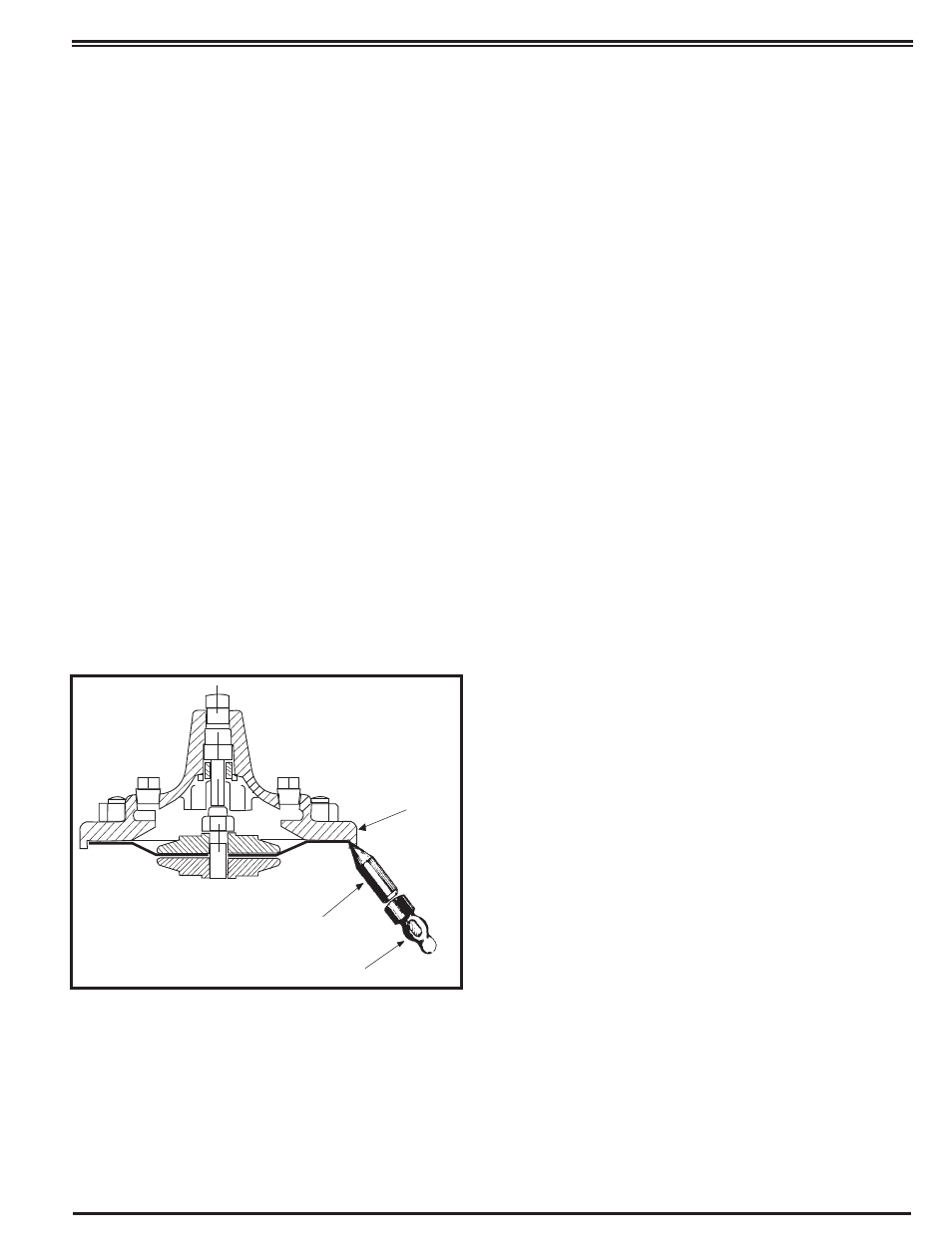
Remove cover nuts and cover. If the valve has been in service
for any length of time' chances are the cover will have to be
loosened by driving upward along the edge of the cover with a
dull cold chisel. See Figure 1.
NOTE:
When block and tackle or a power hoist is to be used to lift the
valve cover insert a proper size eye bolt in place of the center
cover plug. Pull cover straight up to keep from damaging the
power unit stem bearing and upper stem.
Power unit body can now be lifted from the valve body. The
stem with diaphragm will be removed with the power unit body.
The disc retainer assembly with lower stem will separate
(check feature) from the upper stem and power unit body.
Valve Cover
Hammer
Dull Cold Chisel
(Angle upward as
much as possible)
FIGURE 1.