Cla-val, Dimensions – Cla-Val 60-11/660-11 Technical Manual User Manual
Page 12
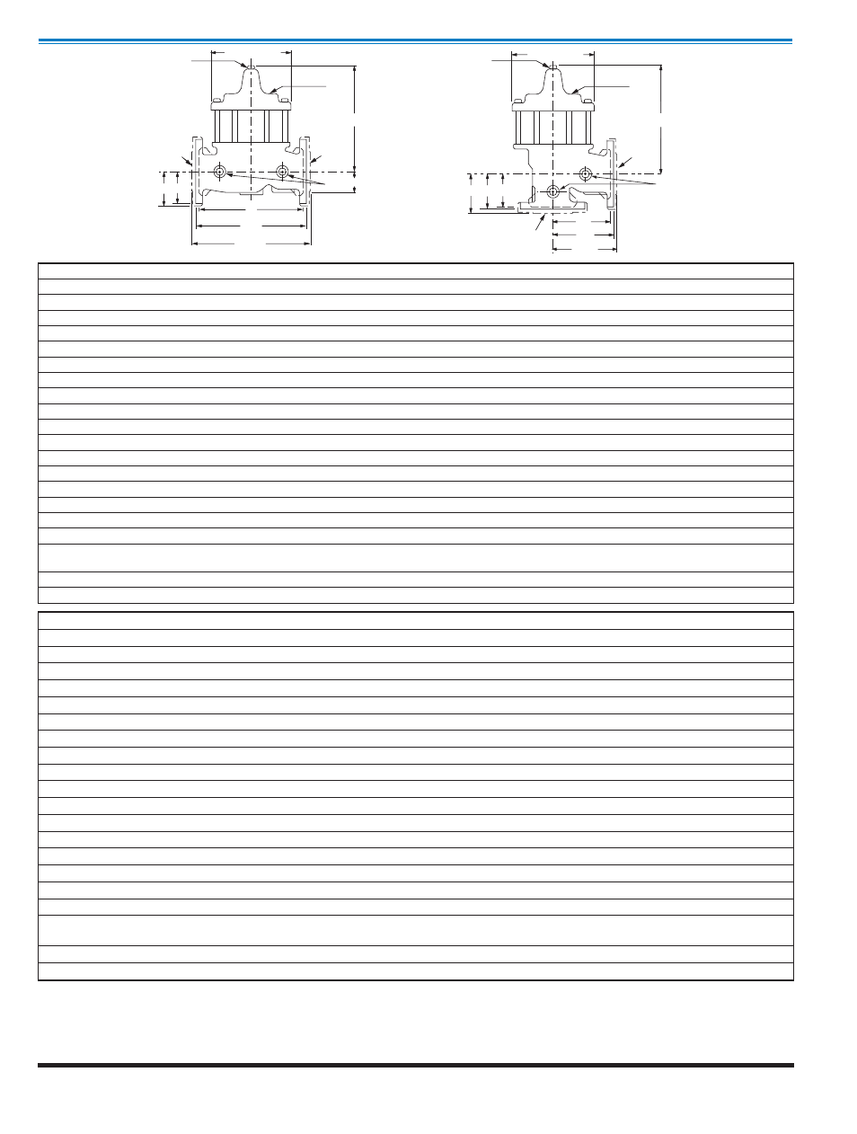
B (DIAMETER)
J
K
INLET
OUTLET
FF F
A
AA
AAA
C
E
H
INLET
GGG GG G
D
DD
DDD
B (DIAMETER)
J
OUTLET
H
C
K
Model 100-03
100-03 (Globe)
100-03 (Angle)
Dimensions
Cla-Val Control Valves operate with maximum efficiency when mounted in horizontal piping with the main valve cover UP, however, other posi-
tions are acceptable. Due to component size and weight of 8 inch and larger valves, installation with cover UP is advisable. We recommend
isolation valves be installed on inlet and outlet for maintenance. Adequate space above and around the valve for service personnel should be
considered essential. A regular maintenance program should be established based on the specific application data. However, we recommend
a thorough inspection be done at least once a year. Consult factory for specific recommendations.
Valve Size
(Inches)
2
1
⁄
2
3
4
6
8
10
12
14
16
A Threaded
11.00
12.50
—
—
—
—
—
—
—
AA 150 ANSI
11.00
12.00
15.00
20.00
25.38
29.75
34.00
39.00
41.38
AAA 300 ANSI
11.62
13.25
15.62
21.00
26.38
31.12
35.50
40.50
43.50
B Dia.
8.00
9.12
11.50
15.75
20.00
23.62
28.00
32.75
35.50
C Max.
10.31
11.19
14.25
18.44
21.81
23.38
29.31
32.12
35.00
D Threaded
5.50
6.25
—
—
—
—
—
—
—
DD 150 ANSI
5.50
6.00
7.50
10.00
12.69
14.88
17.00
19.50
20.69
DDD 300 ANSI
5.81
6.63
7.81
10.50
13.19
15.56
17.75
20.25
21.75
E
1.69
2.06
3.19
4.31
5.31
9.25
10.75
12.62
15.50
F 150 ANSI
3.50
3.75
4.50
5.50
6.75
8.00
9.50
10.50
11.75
FF 300 ANSI
3.75
4.13
5.00
6.25
7.50
8.75
10.25
11.50
12.75
G Threaded
4.00
4.50
—
—
—
—
—
—
—
GG 150 ANSI
4.00
4.00
5.00
6.00
8.00
8.62
13.75
14.88
15.69
GGG 300 ANSI
4.31
4.38
5.31
6.50
8.50
9.31
14.50
15.62
16.50
H NPT Body Tapping
1
⁄
2
1
⁄
2
3
⁄
4
3
⁄
4
1
1
1
1
1
J NPT Cover Center Plug
1
⁄
2
1
⁄
2
3
⁄
4
3
⁄
4
1
1
1
1
⁄
4
1
1
⁄
2
2
K NPT Cover Tapping
1
⁄
2
1
⁄
2
3
⁄
4
3
⁄
4
1
1
1
1
1
Valve Stem Internal
Thread UNF
10-32
1
⁄
4
-28
1
⁄
4
-28
3
⁄
8
-24
3
⁄
8
-24
3
⁄
8
-24
3
⁄
8
-24
3
⁄
8
-24
1
⁄
2
-20
Stem Travel
0.7
0.8
1.1
1.7
2.3
2.8
3.4
4.0
4.5
Approx. Ship Wt. Lbs.
65
95
190
320
650
940
1675
2460
3100
Valve Size
(mm)
65
80
100
150
200
250
300
350
400
A Threaded
279
318
—
—
—
—
—
—
—
AA 150 ANSI
279
305
381
508
645
756
864
991
1051
AAA 300 ANSI
295
337
397
533
670
790
902
1029
1105
B Dia.
203
232
292
400
508
600
711
832
902
C Max.
262
284
362
468
554
594
744
816
889
D Threaded
140
159
—
—
—
—
—
—
—
DD 150 ANSI
140
152
191
254
322
378
432
495
526
DDD 300 ANSI
148
168
198
267
335
395
451
514
552
E
43
52
81
109
135
235
273
321
394
F 150 ANSI
89
95
114
140
171
203
241
267
298
FF 300 ANSI
95
105
127
159
191
222
260
292
324
G Threaded
102
114
—
—
—
—
—
—
—
GG 150 ANSI
102
102
127
152
203
219
349
378
399
GGG 300 ANSI
110
111
135
165
216
236
368
397
419
H NPT Body Tapping
1
⁄
2
1
⁄
2
3
⁄
4
3
⁄
4
1
1
1
1
1
J NPT Cover Center Plug
1
⁄
2
1
⁄
2
3
⁄
4
3
⁄
4
1
1
1
1
⁄
4
1
1
⁄
2
2
K NPT Cover Tapping
1
⁄
2
1
⁄
2
3
⁄
4
3
⁄
4
1
1
1
1
1
Valve Stem Internal
Thread UNF
10-32
1
⁄
4
-28
1
⁄
4
-28
3
⁄
8
-24
3
⁄
8
-24
3
⁄
8
-24
3
⁄
8
-24
3
⁄
8
-24
1
⁄
2
-20
Stem Travel
18
20
28
43
58
71
86
102
114
Approx. Ship Wt. Kgs.
30
43
86
145
295
426
760
1116
1406
CLA-VAL
Copyright Cla-Val 2011 Printed in USA Specifications subject to change without notice.
P.O. Box 1325
• Newport Beach, CA 92659-0325 • Phone: 949-722-4800 • Fax: 949-548-5441 • E-mail: [email protected] • Website cla-val.com
©
N-100-03 (R-3/2011)