Piping, When installing the pump below the tank, When installing the pump above the tank – Pump Solutions Group Neptune Solenoid-driven Diaphragm Metering Pump ARPZ-31_61_12 User Manual
Page 12: Installation
11
Installation
Pump-mounting bolts (2 sets)
Foot valve
Drain cock
Suction-pipe cover
Tank
Relief/air-release hose
Discharge-side joint
Suction-side joint
Suction-side pipe
Relief/air-release port
Main pipe
Anti-siphon check valve
Attach the ceramic
weight (supplied) to
straighten the tube.
Discharge-
side pipe
Injection point
3-way valve
PVDF
U P
Discharge-
side pipe
Discharge-
side joint
Suction-side joint
Suction-side pipe
Suction valve
Injection point
Relief/air-release port
3-way valve
Main pipe
Anti-siphon check valve
Relief/air-release hose
Tank
Installation is described with an example using PZ-31-FEC (PP) and TACMINA tank.
• If the valve has not been opened or clogging by foreign matter has occurred inside the pipe at the discharge side of
the pump, the chemical will gush out from the relief/air-release port. Therefore, always have a relief/air-release hose
installed, and lead its end back into the tank or other container.
• Install a valve for releasing abnormal pressure that has built up inside the discharge-side pipe. The 3-way valve on the
washing water line may be used instead.
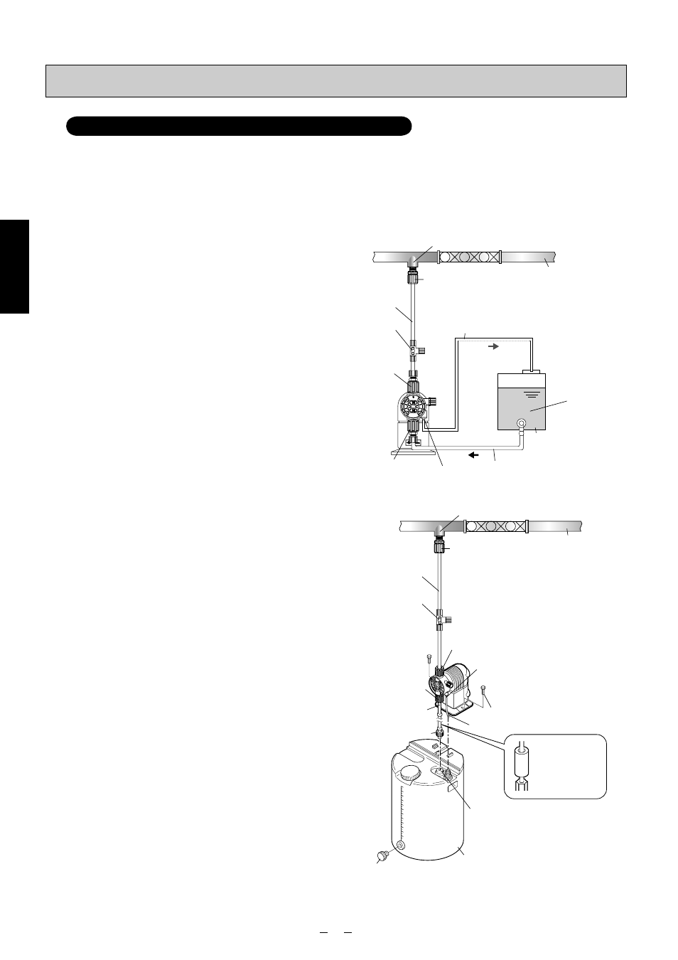
Piping
Model for injection of boiler chemicals: PZ-31-FEC (PP)
■ When installing the pump
below the tank
(1) Connect the suction valve of the tank and the suction-
side joint of the pump using the tube.
(2) Connect the discharge-side joint of the pump and
main pipe (injection point) using the tube. When
doing this, attach the anti-siphon check valve at the
injection-point side end of the tube.
(3) Return the end of the relief/air-release hose which
has already been attached to the relief/air-release
port to the tank or other container.
✽ It is also recommended that a valve, meter, etc. be
installed to make it easy to carry out maintenance
and other such jobs.
■ When installing the pump
above the tank
(1) Using the pump-mounting bolts provided, secure the
pump to the prescribed position on top of the tank.
(2) Pass the suction-side tube with foot valve and
ceramic weight attached through the hole in the
suction-pipe cover on top of the tank, and connect
it to the suction-side joint of the pump. At this time,
adjust the length of the tube and cut it so that the
foot valve is 30 mm higher than the bottom of the
tank.
(3) Connect the discharge-side joint of the pump and
main pipe (injection point) using the tube. When
doing this, attach the anti-siphon check valve at the
injection-point side end of the tube.
(4) Return the end of the relief/air-release hose which
has already been attached to the relief/air-release
port to the tank or other container.
✽ Installing the pump above the tank is not recommend-
ed for chemicals in which air bubbles tend to form.
✽ This pump’s static suction head is −1.5 m for water.
Its suction capability may decrease when the valve
seats inside the pump head are dry.
✽ Be absolutely sure to connect the foot valve provided
to the end of the suction-side hose to prevent dirt
or foreign matter from entering the pump head and
valve seat area.
✽ It is also recommended that a valve, meter, etc. be
installed to make it easy to carry out maintenance
and other such jobs.
07-22_PZ総合取説_E.indd 11
07-22_PZ総合取説_E.indd 11
2008/02/13 8:50:54
2008/02/13 8:50:54