Pump Solutions Group Neptune Series 500 MODEL 481 THRU 547 User Manual
Page 15
12
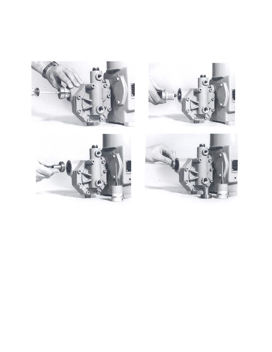
FIGURE VIII
REMOVAL OF CONTROL ROD ASSEMBLY
5. Replace Control Rod “O” Ring (FIG. #517) and Sealing Plate “O” Ring (FIG. #516).
6. Take care when replacing Sealing Plate, (FIG. #518) so as to not damage the Sealing Plate “O” Ring
(FIG. #516).
7. Replace all parts and fill pump with hydraulic fluid per previous instructions.
8. Follow start-up procedure as if starting a new pump.
14.0 REMOVAL OF PUMP HEAD AND REPLACEMENT OF DIAPHRAGM (REFER TO FIGURES IX AND X)
14.0.1 Remove Drain Plug (FIG. #510), and drain hydraulic fluid.
14.0.2 Remove Long and Short Pump Head Bolts [(FIG. #’s 551 and 552) or (P/N 101135 and P/N 101136)
on PVC pumps.] Lift Pump Head [(FIG. #535) or (P/N 000255, P/N 000258) on PVC pump] away from
pump.
14.0.3 Remove and examine Teflon Diaphragm (FIG. #533). Remove and examine the Liquid Side
Diaphragm Backup Place [(FIG. #532) or (P/N 000254, 100245) on PVC pumps.] Replace with new
part, if required. When replacing the Teflon diaphragm, be certain to line it up properly with the sealing
grooves.
14.0.4 To reassemble, reverse the above procedure. Reassembly is facilitated by laying the pump on its side.
Be certain to tighten all bolts evenly. Tighten to 25 ft. lbs. (15ft. lbs. On PVC pump).
14.0.5 Start Up Pump by following Start-Up Procedure per Section II Paragraph 1.0.11 and 6.0.3.