Pump Solutions Group Neptune Series 500 MODEL 481 THRU 547 User Manual
Page 10
7
4.0.1
(Continued)
To protect the external piping system, it is recommended that a relief valve as manufactured by
Neptune Chemical Pump Company, or equal, be placed in the discharge line of the pump. It is
further recommended that this relief valve be piped into return of the tank with clear PVC tubing so
that it can be determined if the solution is by-passing through the valve and returning to the tank,
indicating a line blockage.
Drawing HP-1101 (page 23) illustrates the location of the Internal Relief Valve for Series 500 (FIG.
#527 through #530). See drawing 5024 (page 29) for Series 500-A and 500-E.
The drawing shows a passage connecting the hydraulic fluid reservoir with the hydraulic fluid side of
the diaphragm.
The passage is interrupted by the Relief Valve Poppet (FIG. #527) which is backed up by a Relief
Valve Spring (FIG. #528).
If, during the pump operation, the pressure on the hydraulic fluid side of the pump exceeds the set
pressure of the internal relief valve, the poppet is forced from its seat allowing the hydraulic fluid to
flow back to the reservoir.
4.0.2
To reset the relief valve to a higher pressure, (the relief valve setting cannot be reduced because of
design considerations) instructions are as follows:
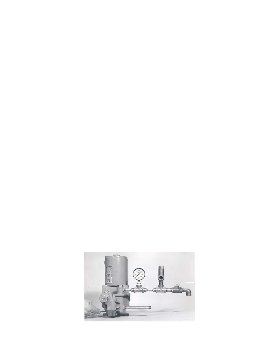
4.0.21 Connect a test set-up as shown in Figure IV below.
4.0.22 Start and run the pump until all air is relieved from the discharge liquid (hand valve open).
4.0.23 Remove Relief Valve Plug (Fig.#530).
4.0.24 Close hand valve; pressure gauge will read the internal relief valve setting which should
agree with the pressure setting on the tag if the pump is new. The desired setting is 100 psi
above the operating pressure of the system into which the pump is injecting. Do not adjust
lower than 200 psi.
4.0.25 To change the relief valve pressure setting, use the 3/16” Allen Wrench to adjust spring
tension by turning Relief Valve Adjusting Screw (FIG. #529).
(1) To increase pressure, turn Relief Valve Adjusting Screw (Fig. #529) in.
(2) To decrease pressure, turn Relief Valve Adjusting Screw (Fig.#529) out.
4.0.26 After resetting or adjusting pressure, replace Relief Valve Plug (Fig. #530).
CAUTION
Never turn Relief Valve Adjusting Screw (Fig. #529) completely in.
Do not attempt to set the internal relief valve more than 200psi in excess of name plate rating.
FIGURE IV