Pump Solutions Group Neptune Series 500 MODEL 481 THRU 547 User Manual
Page 14
11
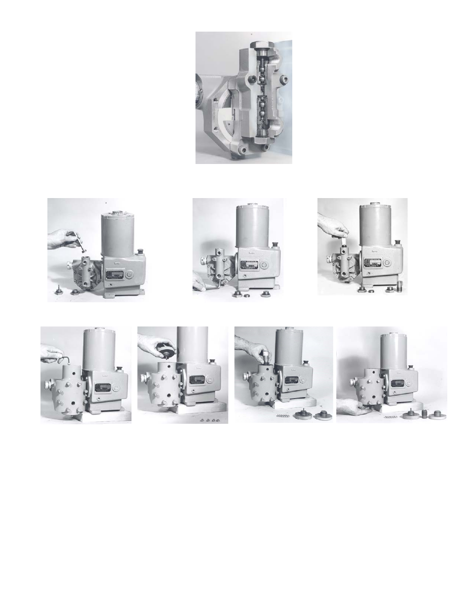
FIGURE V
CUT-AWAY VIEW OF VALVE SECTION, METAL HEAD PUMP
FIGURE VI
VALVE CARTRIDGE REMOVAL, METAL HEAD PUMP
FIGURE VII
VALVE CARTRIDGE REMOVAL, PVC HEAD PUMP
12.0
REPLACING OF VALVE CARTRIDGES (Continued)
13.0
PROCEDURE FOR REPLACING CONTROL ROD “O” RING (fig. #517)
AND SEALING PLATE “O” RING (FIG.#516).
Refer to Figure VIII
1. Remove Drain Plug (FIG. #510) and drain hydraulic fluid.
2. Remove Indicator Plate (FIG. #520) by removing two holding screws.
3. Remove control rod assembly with Control Rod (FIG. #’s 515, 523,524) attached, by turning counter
clockwise and pulling out.
4. Insert 11/16” Hex Socket onto the Sealing Nut (FIG. #526) and screw out of pump in a counter clockwise
direction. Then, remove Sealing Plate (FIG. #518) using a small brass hook to pull loose.