Preliminar y, Wmk 150 • setup guide, cont'd – Extron Electronics WMK 150 User Manual
Page 5
PRELIMINAR
Y
5
WMK 150 • Setup Guide, cont'd
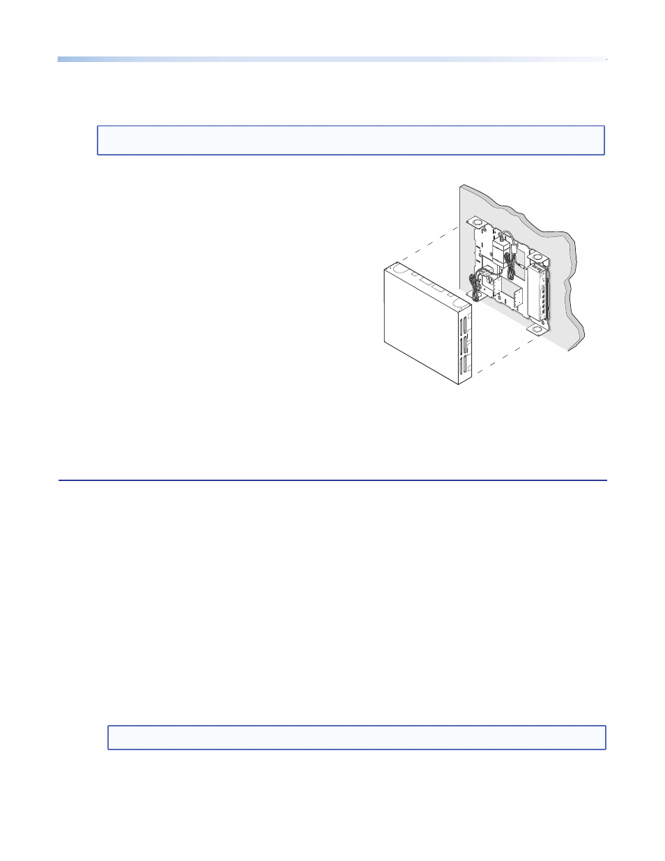
5. Final Installation.
a.
After completing cabling, place the cover over the installed plate, and secure at each corner with the
provided 6-32 button head hex screws.
NOTE:
Ensure any cables exiting the box to a display device and external electrical outlet pass through a
raceway knockout.
b.
Switch on the display device, control device, signal
sources, and then adjust and configure the system as
needed.
For full configuration and setup details, refer to the PoleVault
System Installation Manual, the MLC 104 Plus Series Reference
Manual, and the PVS 305SA User's Manual, all available online
at
www.extron.com
.
PVS 305S
A
POLE
VA
UL
T SWITCHE
R
INPUT SELECTION
1
2
PEA
K
NORMAL
SIGNAL
CONFI
G
34
5
AU
X A
UDI
O
A
UDIO LEVEL ADJUS
T
PA
GING
SENSO
R
SENSITIVITY
VO
ICELIF
T
MI
C
PEAK
NORMAL
SIGNAL
INPU
T
Figure 8.
Attach WMK 150 cover
General Specifications
Mounting
Wall mount .............................. Yes, with included hardware
Maximum load capacity .................. 15 lbs (6.8 kg)
Material ......................................... Steel base plate, aluminum cover
Dimensions
Base plate ................................ 12.9" H x 15.4" W x 2.0" D
(32.7 cm H x 39.0 cm W x 5.1 cm D)
Cover ...................................... 13.0" H x 15.5" W x 2.75" D
(33.0 cm H x 39.4 cm W x 7.0 cm D)
Product weight ............................... 4.5 lbs (2.0 kg)
Shipping weight ............................. 7 lbs (4 kg)
Vibration ........................................ ISTA 1A in carton (International Safe Transit Association)
Regulatory compliance
Safety ...................................... c-UL, UL, OSHPD anchorage pre-approval
Warranty ........................................ 3 years parts and labor
NOTE:
Specifications are subject to change without notice.