Preliminar y, Wmk 150 • setup guide, cont'd, Bg f a – Extron Electronics WMK 150 User Manual
Page 4: Cable the switcher, Cabling the switcher, Config
PRELIMINAR
Y
4
WMK 150 • Setup Guide, cont'd
Figure 7.
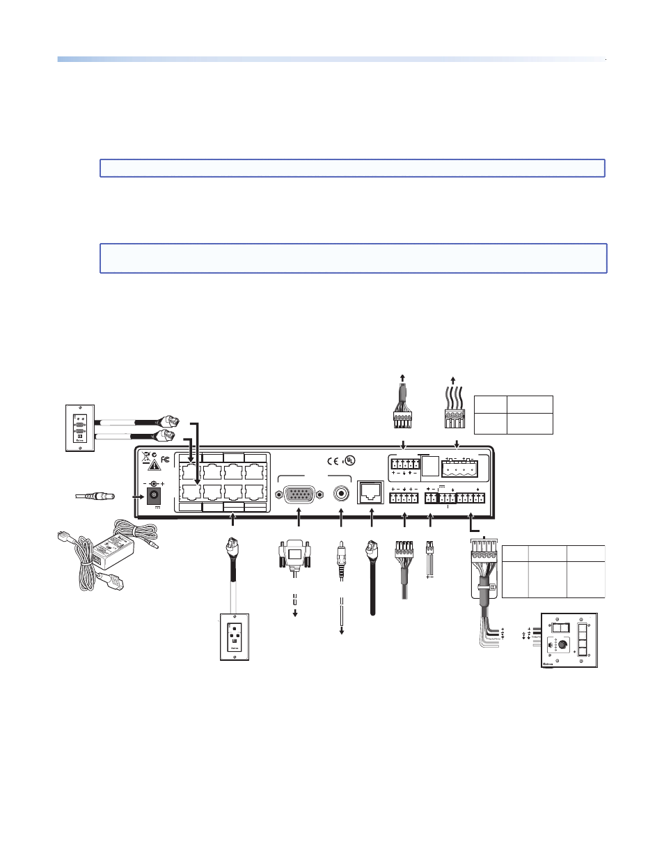
Cabling the switcher
L
R
L
R
L
R
AUX AUDIO
INPUT 5
LINE OUT
VOICELIFT
RECEIVER
PAGING
SENSOR
DO NOT
GROUND
OR SHORT
SPEAKER
OUTPUTS
1B RGB
1A RGB
2B RGB
2A RGB
3B RGB
/VIDEO
4B RGB
/VIDEO
3A RGB
4A RGB
I
N
P
U
T
S
RS-232 MLC/IR
2/4/8
Ohms
CLASS 2 WIRING
AMPLIFIED AUDIO OUT
VOL/MUTE
Tx Rx IR
12V
10V
50mA
POWER
US
LISTED
17TT
AUDIO/VIDEO
APPARATUS
®
RGB
VIDEO
OUTPUTS
CONTROL
N15779
12V
5A MAX
2A RGB
1A RGB
1B RGB
2B RGB
4A RGB
3A RGB
3B RGB
3 VIDEO
4B RGB
4 VIDEO
RGB signal input
(2 CAT 5 cables, A and B
with RJ-45 connectors)
RGB output
to display
RGB #1A
External
Power Supply
(12 VDC, 5 A max.)
Composite
video output
to display
Composite video input
(CAT 5 cable with
RJ-45 connector)
b
g
f
a
RS-232 Control
B
A
+12 VDC
Ground ( )
Transmit (Tx)
Receive (Rx)
Ground ( )
Power
Connector
RCA
Connector
Aux Audio
Input 5
Line out output
(audio)
Red
Positive (+)
Black Negative (-)
Wire Color PVS Terminal
(left and right)
VGA
Connector
RGB #1B
VIDEO #3
CONFIG
DISPLAY
VOLUME
MLC 104 IP PLUS
ON
VCR
DVD
PC
OFF
1
2
3
4
PVT RGB D Plus
PVT CV D
COMPUTER IN
AUDIO
IN
OUT
MONITOR OUT
IR OUT
S G
AUDIO IN
L
R
VIDEO IN
IR OUT
S G
Paging
Sensor
VoiceLift
Receiver
Audio output
to speakers
MLC Wire Colors PVS
Switcher
A (Rx) White A (Tx)
B (Tx) Violet B (Rx)
Ground Drain Wire D (Ground)
Ground Black D (Ground)
12V In Red E +12 V
4. Cable the Switcher
a.
Connect the cables from the PoleVault wallplates, control device (MediaLink
®
Controller), speakers, and
optional accessories (VoiceLift
®
and Page Sensor Kit) to the rear ports of the switcher
(see figure 7 on page 4).
Refer to the PVS 305SA Setup Guide for additional details.
NOTE:
If using a device other than a PVS 305SA (such as a PVS 204SA Plus), refer to that device manual.
b.
Run VGA and composite video cables from the switcher to the output display device through the wall or,
where fitted, the raceway.
c.
Connect the power supply to the switcher and plug it in to the electrical outlet.
NOTE:
If the electrical outlet is outside the WMK, pass the IEC power cable out through one of the
raceway knockouts