Preliminar y, Wmk 150 • setup guide, cont'd – Extron Electronics WMK 150 User Manual
Page 3
PRELIMINAR
Y
3
WMK 150 • Setup Guide, cont'd
Raceway Option
2400
V700
Access
Cutout Option
Accessory Device
Mounting Tabs
Figure 5.
Cabling run options
NOTE:
If using toggle assemblies, see figure 4 for method.
vii.
Align the base plate's slotted mounting holes over
the installed screws, then slide the plate down so
the screw fit into the slots.
viii.
Verify level and position, and tighten down all the
screws to secure the plate flush to the wall.
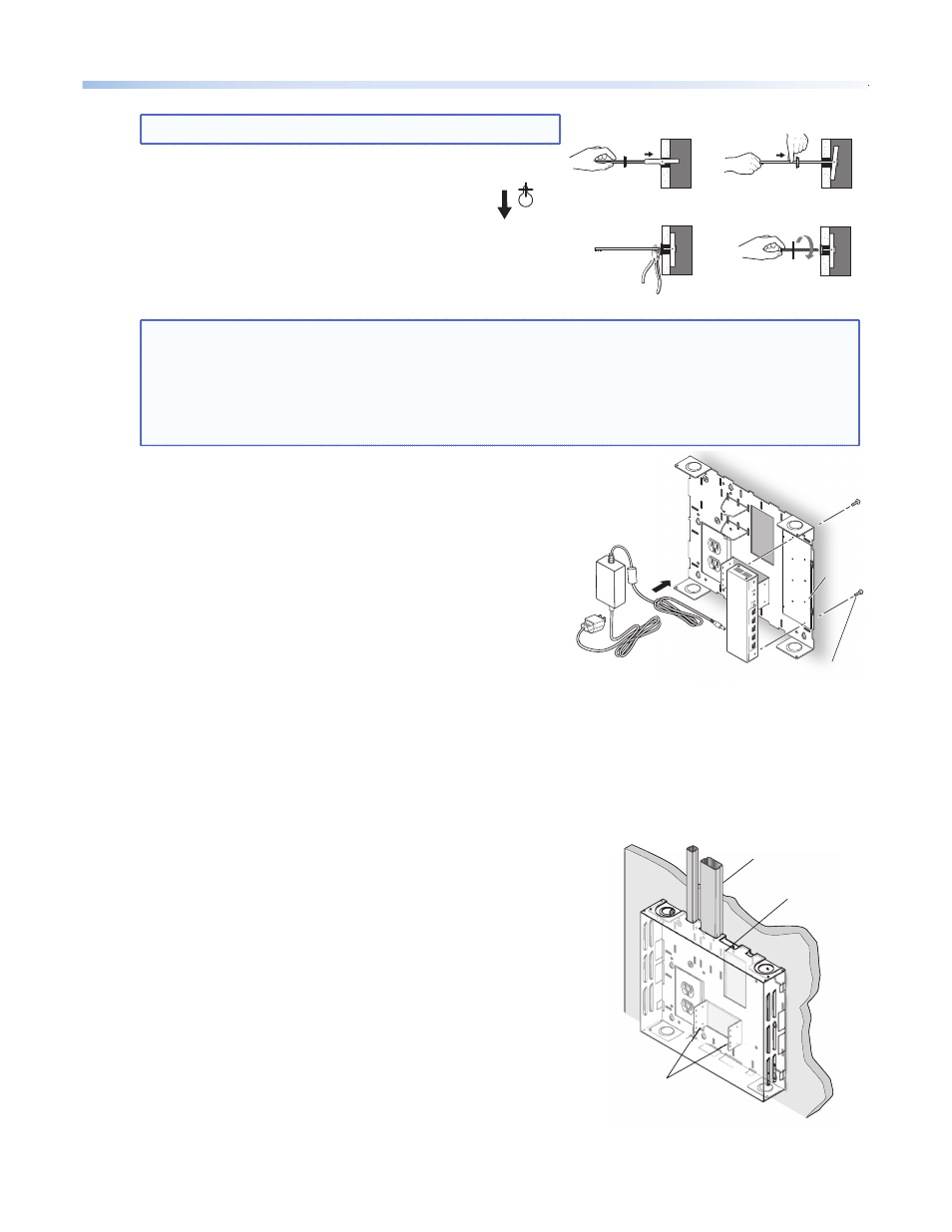
2. Mount the Switcher, Power Supply, and
Accessory Device
NOTE:
Always use a power supply supplied or specified by Extron. Use of an unauthorized power supply
voids all regulatory compliance certification and may cause damage to the supply and the end
product. Unless otherwise stated, the AC/DC adapters are not suitable for use in air handling
spaces or in wall cavities. The installation must always be in accordance with the applicable
provisions of National Electrical Code ANSI/NFPA 70, article 75 and the Canadian Electrical Code
part 1, section 16. The power supply shall not be permanently fixed to a building structure or
similar structure.
a.
Invert the switcher and place it (base up) on a flat surface.
Place the mounting plate flat on the switcher base with
the plate tabs (raised section up) over the edge of the front
panel. Keeping the edge of the plate flush with the front
edge of the switcher, align the two mounting holes in the
switcher base with the corresponding holes on the mounting
plate. Secure the plate to the switcher with the supplied
4-40 x ¼ inch screws.
b.
Secure the switcher mounting plate (with switcher
attached) to the base plate by sliding the two tabs into
the slots at the right edge of the base plate. Secure to
the standoffs with 4-40 x 3/16 inch screws (see figure 5).
c.
Secure the power supply above the electrical outlet cutout
by threading the supplied tie wraps through the loops on the
base plate. Attach it so the cables are easily and safely routed to the electrical outlet and switcher alike.
d.
An optional ¼ rack, 3 inch deep accessory device, such as the Extron HDMI 201 Rx, can be installed on the
WMK 150 base plate. To do so, place the device between the accessory mounting tabs, align the holes on
the tabs and the device, and secure with the supplied 4-40 x 3/16 inch screws.
3. Run Cables
Run signal cables from the proposed PoleVault
®
input wallplates, control
device location, and the speakers to the WMK 150 location. Cables can
be routed behind the walls, or through a surface raceway (for example,
Wiremold
®
V700 or 2400 series) directly to the WMK 150.
3A. If running cable behind the walls:
i.
Run all the cables from the various locations to the WMK and
through the access hole.
3B. If using a surface raceway:
i.
Slide the WMK cover over the base plate, then identify and
mark the most suitable raceway entrance to the WMK 150.
ii.
Run the raceway from the signal source, speaker, and display
locations to the marked raceway entrance at the WMK.
iii.
Remove the WMK cover, and remove the desired knockout.
iv.
Attach the raceway to the wall. Run cables from the sources
and outputs through the raceway to the WMK.
Figure 4.
Toggle assembly installation
a. Grasp handle, collapse
toggle and insert into wall.
b. Slide plastic washer
down into pilot hole.
c. Cut off handle close to wall. d. Hand screw in pan head
bolt until 1/8" gap remains.
Power Supply
PVS 305S
A
POLE
VA
UL
T SWITCHE
R
INPUT SELECTION
1
2
PEAK
NORMAL
SIGNAL
CONFIG
34
5
A
UX
AU
DI
O
A
UDIO LEVEL ADJUS
T
PA
GING
SENSOR
SENSITIVITY
VO
ICELIFT
MI
C
PEA
K
NORMAL
SIGNAL
INPU
T
(2) 4-40 x 3/16" screws
Switcher
Switcher
Mounting
Plate
Figure 6.
Attaching the switcher and power
supply to base plate