Installation and operation, Connections, Rack mounting the tsc 100 – Extron Electronics TSC 100 User Guide User Manual
Page 7
TSC 100 • Installation and Operation
TSC 100 • Installation and Operation
Installation and Operation
2-3
Connections
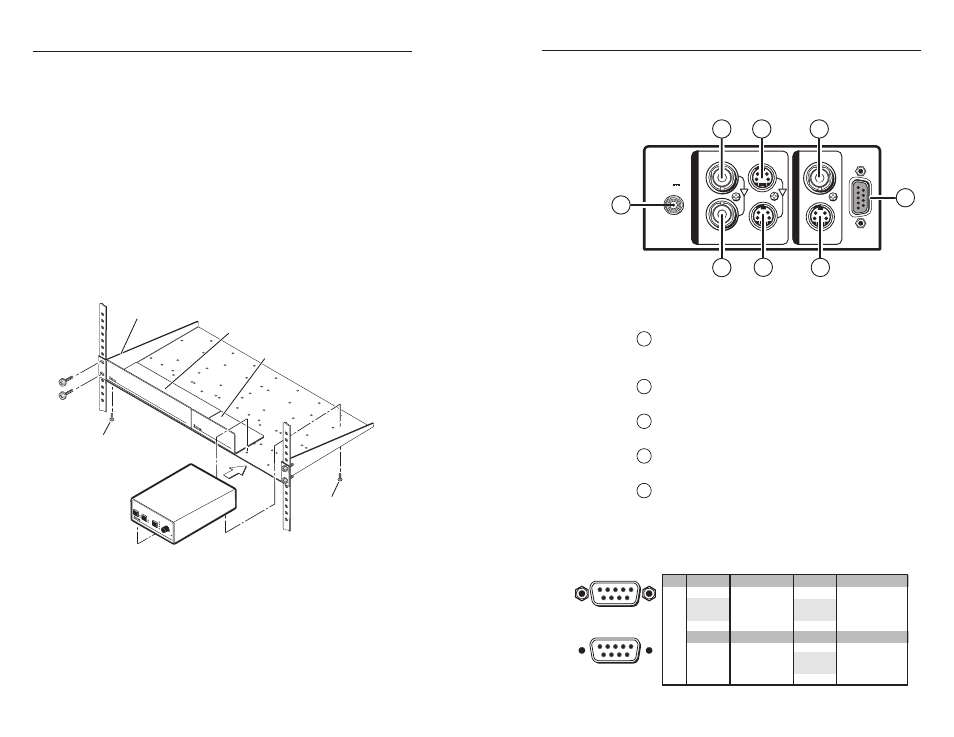
All connections, including power, input and output, and
control, are on the rear panel of the TSC 100. See figure 2.
RS-232/422
COMPOSITE
COMPOSITE
S-VIDEO
S-VIDEO
1
2
POWER
I
N
P
U
T
S
O
U
T
P
U
T
S
9 V
1A MAX
8
6
1
2
3
4
5
7
Figure 2 — TSC 100 rear panel
Rear panel connections
1
Power connection
— Plug the external 9 VDC power
supply into this connector. The power supply is
included with the unit.
2
Input 1 composite BNC connector
— Connect one
BNC female connector for composite video input.
3
Input 2 S-video 4-pin mini DIN connector
— Connect
one 4-pin mini DIN connector for S-video input.
4
Output composite BNC connector
— Connect one
BNC female connector for composite video output.
5
RS-232/422 connector
— Use this connector for RS-232
or RS-422 communications and control. Connect an
RS-232 or RS-422 device (control system or PC
computer) for remote switching between inputs and
remote centering control to this female 9-pin D
connector (see below).
Rack Mounting the TSC 100
In addition to using the TSC 100 on a desktop, it can also be
rack mounted. To rack mount the TSC 100, follow the
installation instructions below.
For optional rack mounting, mount the TSC 100 on a standard,
19" 1U Rack Shelf (Extron part #60-190-01) (figure 1) in one of
four locations on the front of the rack.
1
.
If feet were previously installed on the bottom of the
TSC 100, remove them.
2
.
Mount the TSC on the rack shelf using two 4-40 x 3/16”
screws in opposite (diagonal) corners to secure the
TSC 100 to the shelf.
3
.
Install blank panel(s) or other unit(s) to the rack shelf.
4.
Insert the shelf into the rack, aligning the holes in the shelf
with those of the rack.
Use 2 mounting holes on
opposite corners.
(2) 4-40 x 3/16"
Screws
1U Universal Rack Shelf
Both front false faceplates
use 2 screws.
1/4 Rack Width Front False
Faceplate
1/2 Rack Width Front False
Faceplate
TS
C 100
TR
AN
SCO
DING
STA
NDA
RDS
CO
NV
ERT
ER
1
2
NT
SC
COLOR
TIN
T
BRI
GHT
CONT
RA
ST
PA
L
MAX
MIN
/
ADJ
US
T
INPUT
OUTPUT
PIC
TUR
E
CONTR
OL
S
Figure 1 — Rack mounting the TSC 100
5.
Secure the shelf to the rack using the supplied machine
screws.
This shelf can only be mounted in the front of the rack.
2-2
Female
5
1
9
6
Male
1
5
6
9
Pin
RS-232
RS-422
Description
1
—
2
Tx
Rx-
Tx-
Transmit data
3
Rx
Receive data
4
—
5
Gnd
Gnd
Signal ground
6
—
7
—
Rx+
8
—
Tx+
9
—
—
—
—
—
—
—
—
—
Description
Transmit data (-)
Receive data (-)
Signal ground
Receive data (+)
Transmit data (+)
—
—
—
—
—
—