Base features, Installing the tlp 700tv, Setup guide — tlp 700tv (continued) – Extron Electronics TLP 700TV Setup Guide User Manual
Page 2
Setup Guide — TLP 700TV (Continued)
Base Features
Three adjustable potentiometers in the base that are used
to control sharpness, and gain for both S-video luminance
(Y), and S-video chrominance (C). If a composite video
signal is being used, the gain is controlled by the center
potentiometer (Vid/Y).
To adjust these settings:
1.
Apply power to the unit.
2.
Provide a video input through the MTP RJ-45 connection.
3.
Enter the Setup Menu (see the next page).
4.
Navigate to the Video screen and calibrate the video
settings.
Installing the TLP 700TV
The TLP 700TV comes assembled with a stand that allows it to
be placed on any suitable flat surface. If required, secure the
unit to the top of the desk by drilling two holes through the
desk 5.1 inches (13 cm) apart. Insert two 8-32 screws through
the bottom of the desk into the two holes in the base.
NOTES:
If you are using the MTP video input, this must
be calibrated before you secure the unit to the
flat surface (see Base Features, above).
If you are using the MTP video input, this must
be calibrated before you secure the unit to the
flat surface (see Base Features, above).
1.
For correct operation, connect the power supply provided
to the 2-pole captive screw connector (see
l
in figure 4).
WARNING:
For important information about placing
the power supply, see the Caution in the
Power Connector section of the Reference
Manual.
CAUTION:
Extron strongly recommends securing the
power supply cables to the base of the unit
with a zip tie.
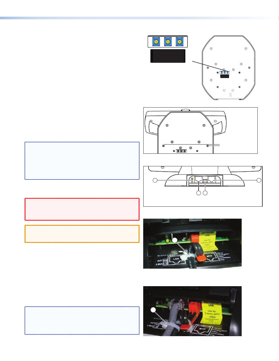
2.
Form a loop from the power supply cable that fits into
the gap between the tail to the captive screw connector
and the raised hook in the base of the unit (see figure 5).
3.
Secure the power cable loop to the base of the unit with
a zip tie (
n
).
4.
Insert the network cable into the RJ-45 socket (
k
) closest
to the green and yellow LEDs (
j
). See figure 4.
5.
If required, insert the twisted pair connection for the
Extron MTP Transmitter into the MTP RJ-45 socket (
m
).
See figure 4.
NOTES:
The minimum distance from the MTP
transmitter to the TLP is 50 feet.
Extron recommends securing all cables with a
zip tie (see
o
in figure 6).
C
Gain
Vid/Y
Gain
Sharp
33-1814-01
A
C
Gain
Vid/Y
Gain
Sharp
33-1814-01
A
Figure 2.
Base features
C
Gain
Vid /
Y
Gain
Sharp
33-1814-01
A
Secure TLP 700TV to
the desk top with
8-32 screws, using these
two holes in the base.
Figure 3.
Securing the TLP 700TV to a desktop
10
13
11 12
W
Do not connect the MTP socket (
m
) to a computer data or
telecommunications network.
Figure 4.
TLP 700TV rear panel connections
14
Figure 5.
Securing the power cable
15
Figure 6.
Securing all cables