Sme 100 • setup guide (continued), Powering up, Step 4 — connect rs-232 control device (optional) – Extron Electronics SME 100 Setup Guide User Manual
Page 2: Step 5 — connect the sme 100 to the network, Step 7 — power on the sme 100 and all devices
2
SME 100 • Setup Guide (Continued)
EXTRON
ELECTRONICS
1
sec.
All input LEDs flash
once in sequence.
1
sec.
2
sec.
Last active input
LED remains lit
(here input 3).
= flashing
Key
1
3
= lit
SME 100 HD/SD
FW V2.00
45
sec.
NOTE:
The information shown in the default display cycle
may differ depending on the active input and type of video signal.
SME 100 HD/SD
INITIALIZING
LOADING
FIRMWARE
30
sec.
~4
sec.
Power
On
Default Display Cycle
2 sec.
2
sec.
In#1 YUVp/HD
480p
640 x 480
OUTPUT A/V
BR 521 Kbps
UNICAST RTP
2
sec.
SME 100 HD/SD
FW V2.00
2 sec.
In#1 YUVp/HD
31kHz 60Hz
2
sec.
z
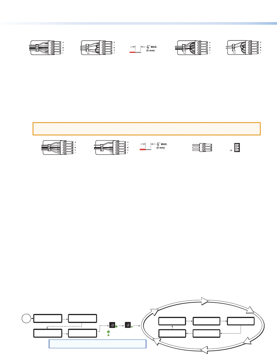
Connect audio input devices to the audio captive screw connectors (inputs 1 through 3;
h
) using cables with balanced or
unbalanced 3.5 mm, 5-pole captive screw connectors. See the image below to wire the connectors.
Unbalanced Stereo Input
Balanced Stereo Input
Tip
Ring
Tip
Ring
LR
Sleeves
Tip
Sleeve
Sleeve
Tip
LR
Unbalanced Mono Input
Balanced Mono Input
(high impedance)
Tip
Ring
LR
Sleeve
Tip
Sleeve
LR
Do not tin the wires!
Step 3 — Connect Buffered Loop Output Devices (Optional)
If necessary, connect output devices to the following buffered loop connectors. Buffered loop connectors output the input video
that is connected to a similar input connector (for example, BNC buffered loop connectors output BNC video).
z
Connect a video output device to the component, S-video, composite BNC buffered loop connectors (
c
).
z
Connect a video output device to the 15-pin HD buffered loop connector (
e
).
z
Connect a high resolution digital output device to the DVI buffered loop connector (
g
).
z
Connect audio output devices to the buffered loop audio captive screw connectors (
i
) using cables with balanced or
unbalanced 3.5 mm, 5-pole captive screw connectors. See the image below to wire the connectors.
ATTENTION: For unbalanced audio, connect the sleeves to the ground contact. DO NOT connect the
sleeves to the negative (–) contacts.
Balanced Audio Output
Tip
Ring
Tip
Ring
LR
Sleeves
Unbalanced Audio Output
Tip
Tip
LR
Sleeves
Do not tin the wires!
Tx
Rx
Ground
Receive
Transmit
RS-232 Connected Device
SME100 (
j
)
Step 4 — Connect RS-232 Control Device (Optional)
If necessary, connect a host computer or control system to the RS-232 connector (
j
). Use this port to send Simple Instruction
Set (SIS™) commands to the SME 100 for device configuration and control. The default protocol for this port is:
9600 baud rate, no parity bit, 8 data bits, 1 stop bit, and no flow control (handshaking).
Step 5 — Connect the SME 100 to the Network
Connect one end of an RJ-45 cable to the Ethernet connector (
l
) on the SME 100. Connect the other end of the RJ-45 cable to
a router or switch to connect the SME 100 to a network.
The LEDs on the Ethernet connector indicate the status of the network connection. The green LED lights when connected to a
network. The amber LED flickers as the SME 100 actively communicates with a network.
Step 6 — Connect Control PC and Viewing Devices to the SME 100 Network
Connect one end of an RJ-45 cable to a control PC or viewing device. Connect the other end of the RJ-45 cable to a router or
switch to connect the control PC or viewing device to the network.
Step 7 — Power On the SME 100 and All Devices
Connect a standard IEC power cord into the AC power connector (
a
) of the SME 100 and plug it to a 100 to 240 VAC,
50 Hz or 60 Hz power source. Connect the power cords of the input and output devices and turn them on.
Powering Up
When applying power to the SME 100, the unit undergoes a self-testing sequence (see the image below). After the testing
sequence is complete (and when the device is not being configured), the default display cycle is shown on the LCD display.
The default display cycle shows the model name/firmware version, active input/output signal format, active input/horizontal and
vertical scan rate, stream mode/output resolution,
and stream method/AV bit rate in kilobits per second (Kbps).