Extron Electronics SME 100 Setup Guide User Manual
Sme 100 • setup guide, Rear panel overview, Installation
1
SME 100 • Setup Guide
The Extron SME 100 is a live streaming media encoder that interfaces with DVI, RGB, HDTV,
and standard definition signals for delivering media over IP networks. It features a three input video and audio switcher, plus
buffered loop-throughs for simplified integration into AV systems. The SME 100 uses H.264 / MPEG-4 AVC encoding to output an
IP stream over the Internet (or over an intranet) that can easily be decoded and viewed on PCs or H.264 compatible devices.
The
SME 100 HD (part number 60-1061-01) supports both high definition and standard definition output rates. The SME 100 SD
(part number
60-1061-02) supports standard definition output rates only.
This guide provides basic instructions for an experienced installer to set up and operate the SME 100. Installation and service
must be performed by authorized personnel only.
NOTE: See the SME 100 User Guide for complete installation, configuration, operation, and mounting
information. The user guide is available at
www.extron.com
.
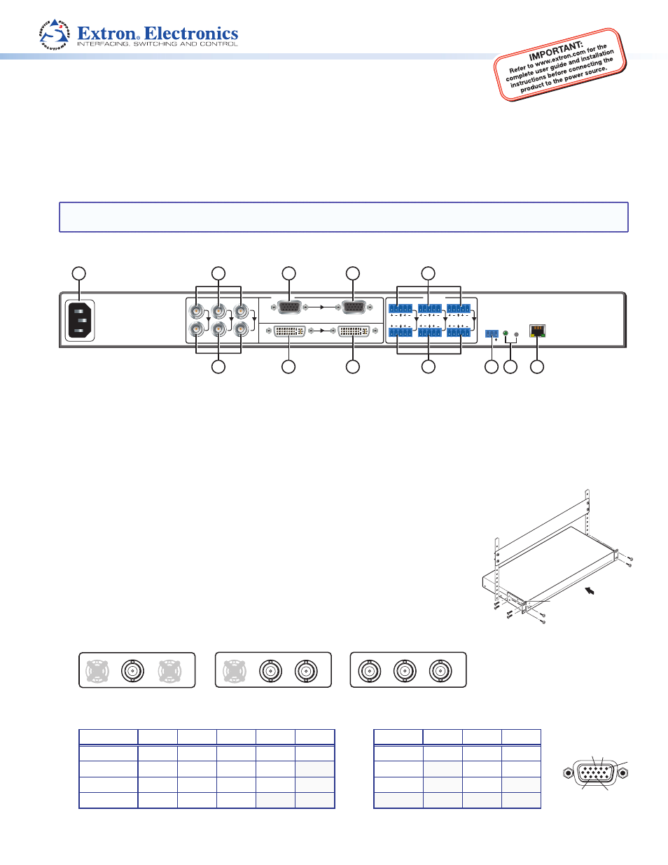
Rear Panel Overview
RS-232
RESET
Tx Rx
100-240VAC
50/60 Hz
0.5A MAX
R-Y
Y/
VID
B-Y/
C
RGB/R-Y,Y,B-Y/YC/VID
DVI-D
BUFFERED LOOP
BUFFERED LOOP
1
1
2
INPUTS
AUDIO
3
L
R
2
L
R
3
L
R
LAN
ACT LINK
1
4
5
3
2
6
7
10
8
9
12
11
a
AC power connector
g
DVI buffered loop connector
b
Component, S-video, composite BNC connectors (input 1)
h
Audio captive screw connectors (inputs 1 – 3)
c
Component, S-video, composite BNC buffered loop connectors
i
Buffered loop audio captive screw connectors
d
15-pin HD connector (input 2) with EDID emulation
j
RS-232 connector
e
15-pin HD buffered loop connector
k
Reset button and LED
f
DVI connector (input 3) with EDID emulation
l
RJ-45 Ethernet connector
Installation
Step 1 — Mount the SME 100
Turn all devices off and unplug their power cords. Verify that the SME 100 is disconnected from
the power source. Mount the SME 100 to a rack using the mounting brackets included with the
unit (see image at right).
Step 2 — Connect Input Devices
Connect input devices to at least one of the following connectors.
z
Connect a video input device to the component, S-video, or composite BNC connectors
(input 1;
b
). See the examples below to connect the necessary signal format.
1
B-Y/
C
Y
/
VID
R-Y
1
R-Y
Y
/
VID
B-Y
/
C
1
Y/
VID
B-Y/
C
R-Y
S-video (YC)
Component Video (Y, R-Y, B-Y)
Composite Video
z
Connect a video input device to the 15-pin HD connector (input 2;
d
). See pin configurations below.
Signal
Pin 1
Pin 2
Pin 3
Pin 13
Pin 14
Signal
Pin 1
Pin 2
Pin 3
RGBHV
R
G
B
H
V
YUV
R-Y
Y
B-Y
RGBS
R
G
B
S
S-video
Y
C
RGBcvS
R
G
B
S
Video
Vid
RGsB
R
Gs
B
z
Connect a high resolution digital input device to the DVI connector (input 3;
f
).
Rack Mount
Bracket
1
2
13
3
14