Remote contr ol and optimizing the v ideo, cont’d – Extron Electronics MTPX Plus Series Setup Guide User Manual
Page 18
Refer also to the
MTPX Plus User’
s Manual
at
www
.extron.com
.
Refer also to the
MTPX Plus User’
s Manual
at
www
.extron.com
.
Command
ASCII command
(host to switcher)
Response
(switcher to host)
Additional description
Input signal level and peaking and auto calibrate
Set input signal level
EX!
*
X^
Ipek
}
Ipek
X!
*
X^]
Set a specific pre-peak level for the TP
input.
Increment input peaking
EX!
+Ipek
}
Ipek
X!
*
X^]
Increase the input pre-peaking level by 1.
Decrement input peaking
EX!
-Ipek
}
Ipek
X!
*
X^]
Decrease the pre-peaking level by 1.
Read input peaking setting
EX!
Ipek
}
X^]
Execute auto calibration
EX!
*0AADJ
}
Aadj
X!
*2
]
{start}
Qik
]
{tie creation}
Aadj
X!
*
X&]
{finished}
Ipek
X!
*
X^]
{new value}
Tie input
X!
to output 1 and auto adjust
the peaking on input
X!
. The
X&
value
in the response reports whether the
adjustment value was within or outside of
the threshold.
N
Before issuing the auto calibration command:
1. Disconnect the power and RJ-45 cables at the MTP transmitter connected to
X!
.
2. Connect the two cables to the included MTP signal generator.
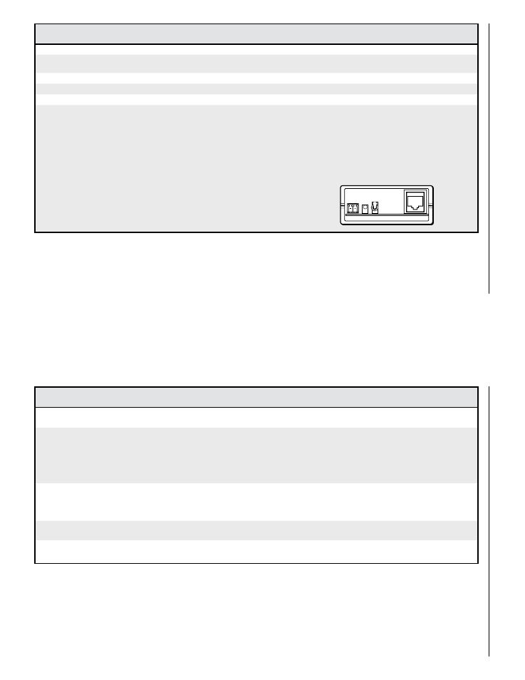
3. If the input cable is longer than 300 feet (90 m), place the Pre-Peak switch on the
MTP signal generator to on (up when the signal generator‘s RJ-45 connector is to the
right as shown at right).
N
The MTP signal generator does not work on cable lengths over 400 feet (120 m). Set the
level and peaking to its maximum value of 255.
Pre-Peak
is on.
Command
ASCII command
(host to switcher)
Response
(switcher to host)
Additional description
Input skew adjustment
N
For the MTPX Plus, these commands apply to inputs 5 through 12 only.
Set all input skew adjustment
values
EX!
*
X*
*
X*
*
X*
Iseq
}
Iseq
X!
*
X*
*
X*
*
X*]
Set a specific skew adjustment for the TP
input.
X*
values are listed in RGB order.
Example:
E
2*0*0*4Iseq
}
Iseq02*0*0*4
]
Set the skew settings for input 2 as follows:
Red = 0 ns
Green = 0 ns
Blue = 8 ns (delayed 8 ns)
Increment one input skew
adjustment value
EX!
*
X(
+Iseq
}
Iseq
X!
*
X*
*
X*
*
X*]
Increase the
X(
skew plane adjustment for
input
X!
by 1 step (2 ns).
Example:
E
2*2*+Iseq
}
Iseq02*0*0*5
]
Increase the blue skew input for 2 by 2 ns
(from 8 ns to 10 ns).
Decrement one input skew
adjustment value
EX!
*
X(
-Iseq
}
Iseq
X!
*
X*
*
X*
*
X*]
Decrease the
X(
skew plane adjustment for
input
X!
by 1 step (2 ns).
Read input skew adjustment
values
EX!
Iseq
}
X*
*
X*
*
X*]
N
X!
= Input number
01 – (maximum number of inputs for your model)
X^
= Input signal level/peaking range
000 – 255
X&
= Threshold
0 = outside of threshold
1 = within threshold
N
X!
= Input number
01 – (maximum number of TP inputs for your model)
X*
= Skew adjustment range
00 – 31 (each step = 2 ns)
X(
= Video plane
0 = red
1 = green
2 = blue
MTPX P
lus Series • Remote Contr
o
l and Optimizing the V
ideo
Remote
Contr
ol
and
Optimizing
the
V
ideo,
cont’d
4-6
MTPX P
lus Series • Remote Contr
o
l and Optimizing the V
ideo
4-7