Teamwork kits • installation guide (continued), Installation, Install the ac power modules in the cable cubby – Extron Electronics TeamWork 601i Kits Installation User Manual
Page 4
TeamWork Kits • Installation Guide (Continued)
4
Installation
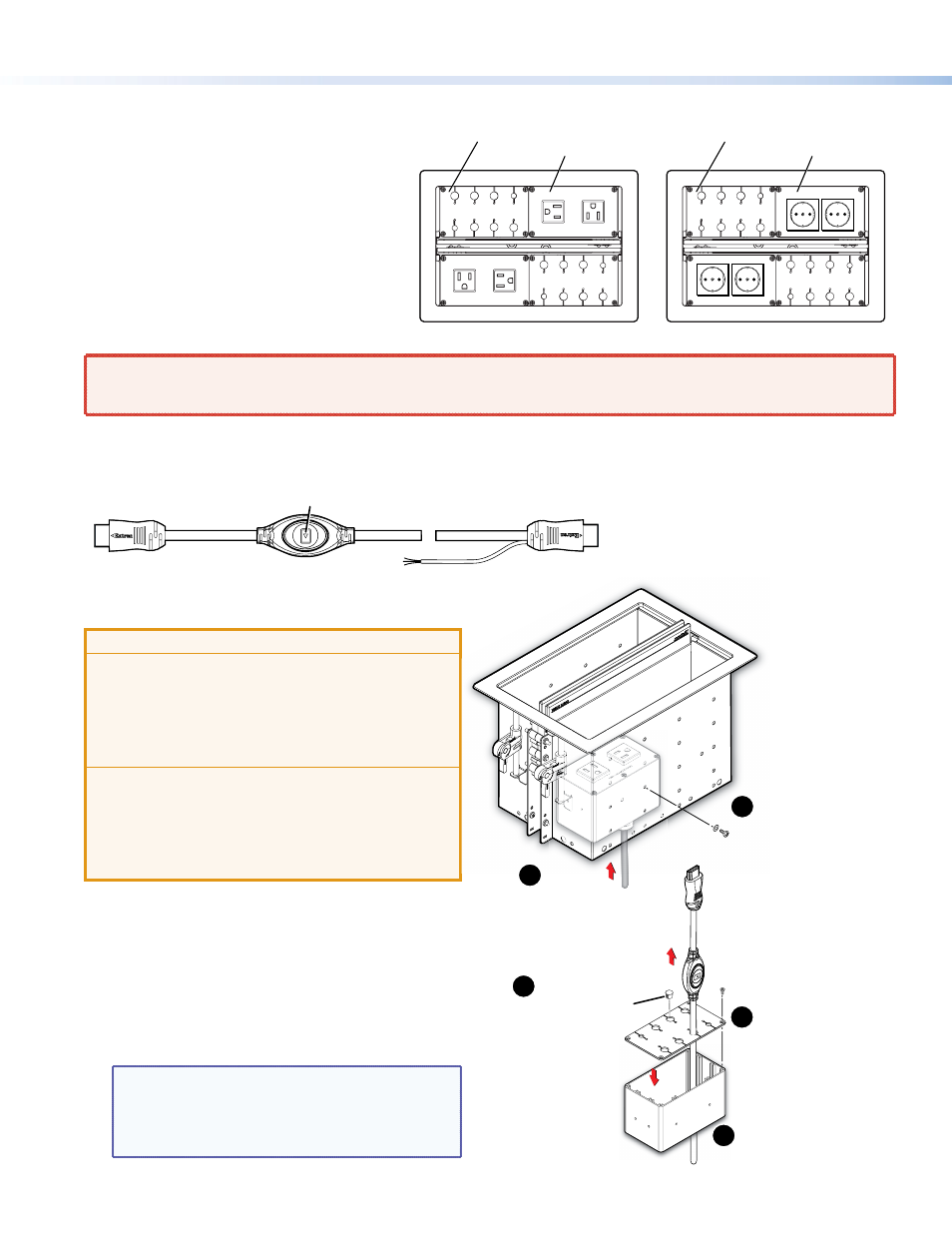
Install the AC Power Modules in the
Cable Cubby
Detailed instructions are in the Cable Cubby
Installation Guide.
Extron recommends the layout shown to the right
with the two power modules diagonally opposite
each other and the cable pass-through modules
diagonally opposite each other.
Slide the power modules in position (
1
in the figure
below, right) and secure them with the provided
#6-32 mounting screws and star washers (
2
).
WARNING:
Risk of electric shock: To ensure good electric grounding, you must use the star washers with the screws.
AVERTISSEMENT:
Risque de choc électrique: Afin d’assurer une mise à la terre correcte, vous devez fixer les modules
d’alimentation au Cable Cubby à l’aide de vis et de rondelles en étoile.
Install the Cable Pass-through Modules and “Show Me” Cables
INPUT
(to source device)
OUTPUT
(to switcher)
Three-conductor Pigtail
(for contact closure
and tally)
Top
of Cable Cubby
Bottom
of Cable Cubby
Share Button
ATTENTION:
•
The end with the button and LED connects to the
input devices and must come out of the top of the
Cable Cubby.
•
Le bout avec le bouton et la LED se connecte
aux appareils d’entrée et doit ressortir du haut du
Cable Cubby.
•
The end with the three-conductor pigtail connects
to the switcher and must come out of the bottom of
the Cable Cubby.
•
Le bout avec le mini câble à trois conducteurs se
connecte au sélecteur et doit ressortir du bas du
Cable Cubby.
1.
Insert cables into the grommet plate (
3
).
2.
Secure the grommet plate to the connectivity bracket
(
4
).
3.
Plug any unused holes (
5
).
4.
Insert the cable pass-through modules into the Cable
Cubby from underneath and secure them in position
with the provided #6-32 mounting screws and star
washers.
NOTE:
The diagrams on this page show how to
install HDMI “Show Me” cables in the cable
pass-through modules. If you are using VGA or
mini DisplayPort “Show Me” cables, install them
in exactly the same way.
240V ~ 50-60Hz 10A MAX TOTAL
240V ~ 50-60Hz 10A MAX TOTA
L
125V ~ 50-60Hz 12A MAX TOTAL
125V ~ 50-60Hz 12A MAX TOTA
L
US Model
Power Modules (2)
International Model
Cable Pass-through
Modules (2)
Power Modules (2)
Cable Pass-through
Modules (2)
“Show Me” Cable
Insert cables through the bottom
of the connectivity bracket and into
the holes of the grommet plate.
Secure the grommet plate
on the connectivity bracket.
Snap the included hole
plugs into any unused
holes.
Slide the AC power modules
under the Cable Cubby.
2
1
3
4
5
Secure the modules using
two of the provided
mounting screws and
star washers.