Teamwork kits • installation guide (continued) – Extron Electronics TeamWork 601i Kits Installation User Manual
Page 2
TeamWork Kits • Installation Guide (Continued)
2
TeamWork 601 and TeamWork 601i Kits Included Parts
TeamWork 601
TeamWork 601i
Video switcher
1 (MPS 601)
2 VGA and 4 HDMI inputs
1 (MPS 601)
2 VGA and 4 HDMI inputs
System controller
1 (IPL T PC1)
1 (IPL T PC1i)
Cable Cubby 1400
1
1
Power modules
2 US modules included
(4 AC outlets total)
Sold separately
HDMI “Show Me” cables
4
4
VGA “Show Me” cables
2
2
HDMI cable
1
1
Switcher control cable
1
1
IEC C14 male power cord plug (see instructions below)
1
Installation Guide
TeamWork 601 and 601i Kits Installation Guide
IEC C14 Male Power Cord Plug Installation
When using the IPL T PC1i system controller (International TeamWork kits) you must replace the power plug on the display with
the provided IEC C14 male power cord plug. This plug has a maximum current rating of 10 A and a maximum voltage of 250 VAC.
WARNING:
High Voltage. Failure to follow these instructions may result in serious injury.
AVERTISSEMENT:
Haute tension. Le non-respect de ces instructions peut provoquer des blessures graves.
•
Installation and service of the power cord plug must be performed by authorized personnel only.
•
L’installation et l’entretient de la fiche du cordon d’alimentation doivent être effectués uniquement par le personnel
autorisé.
•
Observe the correct wire polarity.
•
Respecter la polarité correcte des câble.
•
Disconnect the power from the display or any other device before you begin installation.
•
Débranchez l’alimentation de l’appareil d’affichage ou de tout autre appareil avant de commencer l’installation.
NOTE:
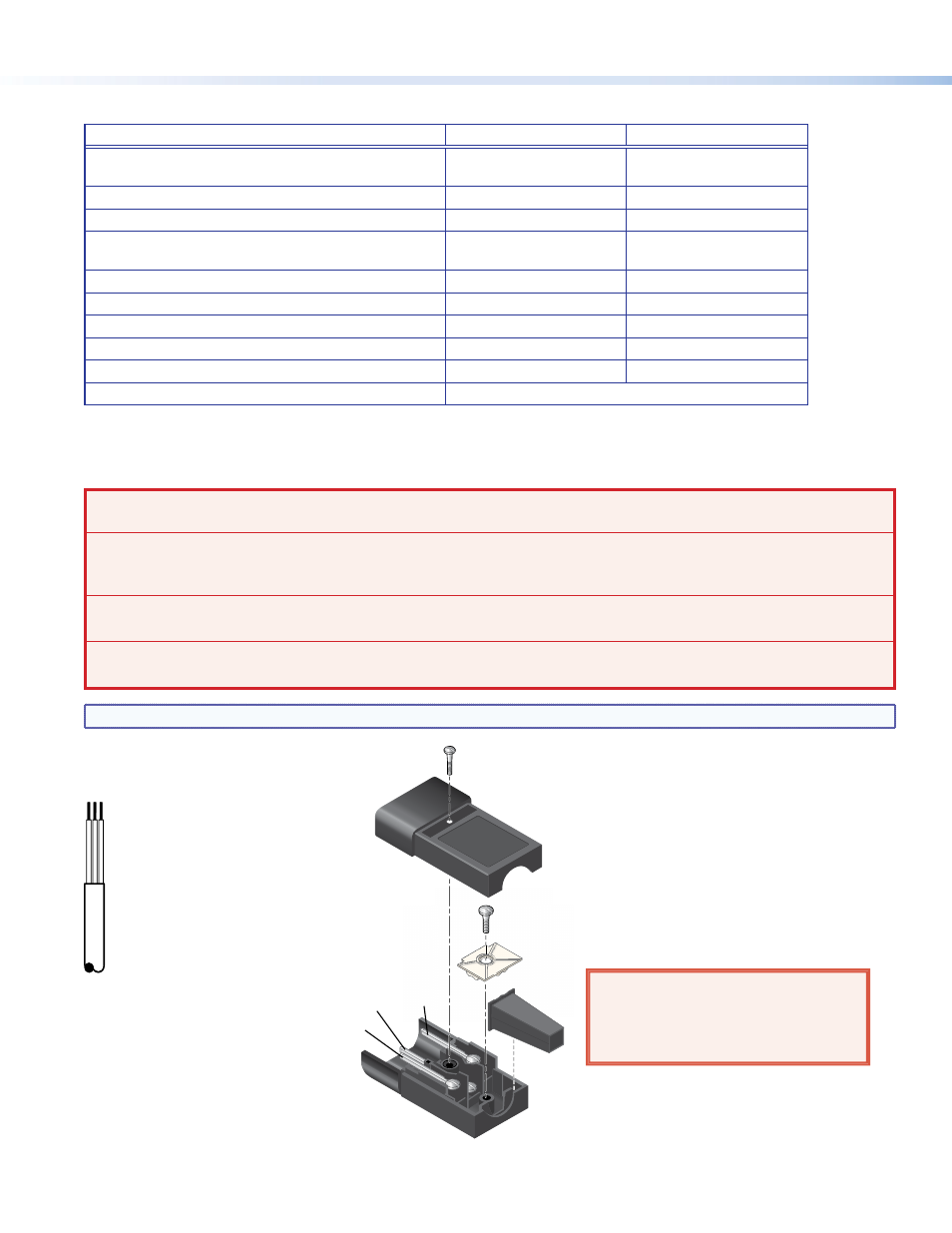
The power cord plug shown in the figure is for illustration only. The plug provided may not look exactly the same.
4. Loosen the screw and remove the top
plate.
1. Cut the existing plug from the
power cord.
2. Remove a suitable amount of
the outer sheath from the
power cord.
Individual wires should not
extend from the back of the
strain relief after the plug is
installed.
3. Strip a suitable amount of the
jacket from the three wires.
There should be just enough
bare metal to wrap around
the screw in step 7.
5. If required, loosen the white plastic wire
clamp.
Ground
(Earth) Neutral
Live
(Hot)
6. Thread the cord through the strain relief.
7. Use a flat head screwdriver to secure the
individual wires to the correct connector.
8. Secure the wires by tightening the white
plastic wire clamp.
9. Reattach the top plate and screw that were
removed in step 4.
AVERTISSEMENT: Respecter la polarité
correcte des câble (voir l'illustration
à gauche).
WARNING: Observe the correct wire
polarity (see the diagram to the left).
L G N