Rear panel features, Setup menu, Extron contact information – Extron Electronics TLP Pro 520M Setup Guide User Manual
Page 4: Tlp pro 520m • setup guide (continued), Attention
4
68-2153-50 Rev. A
04 14
Extron Headquarters
+1.800.633.9876 (Inside USA/Canada Only)
Extron USA - West
Extron USA - East
+1.714.491.1500 +1.919.850.1000
+1.714.491.1517 FAX
+1.919.850.1001 FAX
Extron Europe
+800.3987.6673
(Inside Europe Only)
+31.33.453.4040
+31.33.453.4050 FAX
Extron Asia
+65.6383.4400
+65.6383.4664 FAX
Extron Japan
+81.3.3511.7655
+81.3.3511.7656 FAX
Extron China
+86.21.3760.1568
+86.21.3760.1566 FAX
Extron Middle East
+971.4.299.1800
+971.4.299.1880 FAX
Extron Korea
+82.2.3444.1571
+82.2.3444.1575 FAX
Extron India
1800.3070.3777
(Inside India Only)
+91.80.3055.3777
+91.80.3055.3737 FAX
© 2014 Extron Electronics All rights reserved. All trademarks mentioned are the property of their respective owners.
www.extron.com
Status
Display
Audio
Advanced
Exit
Network
Info
Model:
TLP Pro 520M
Part Number: 60-1185-02
Firmware
Version:
1.00
PoE Status:
On
Network
IP Address:
DHCP:
Host Name:
Off
192.168.254.251
TLP-AB-CD-EF
Display
Resolution:
Project:
Sleep Timer:
800x480
N/A
5 Minutes
Audio
Master Volume:
Master Mute:
Off
99
Advanced
Controller IP:
N/A
Project Size:
N/A
TLP Pro 520M • Setup Guide (Continued)
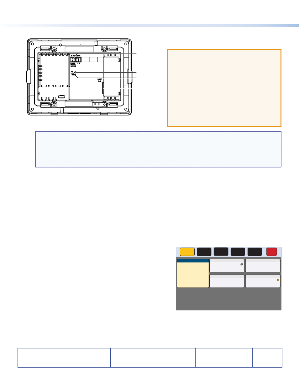
Rear Panel Features
A
B
C
D
E
Figure 3.
TLP Pro 520M Rear Panel
Figure 4.
Setup Menu
A
Power connector — Connect a 12 VDC, 1.0 A power
supply (not included) to this 2‑pole, 3.5 mm captive screw
connector.
ATTENTION:
The TLP Pro 520M can use a 12
VDC desktop power supply and is also Power
over Ethernet (PoE 802.3af, class 3) compliant. Do
not connect either power supply before reading
the Attention in the Power Supply section of the
TLP Pro 520 Series User Guide.
ATTENTION:
Le TLP Pro 520M peut utiliser une
source d’alimentation externe 12 Vcc, et est
également compatible avec l’alimentation POE
via Ethernet (PoE 802.3af, classe 3). Ne branchez
pas de sources d’alimentation externes avant
d’avoir lu les mises en garde dans la section
« Power Supply » du TLP Pro 520 Series User
Guide.
NOTE:
•
The TLP Pro 520M ships without a power supply. Either the 12 VDC, 1.0 A power supply or the power injector
must be purchased separately.
•
If a 12 VDC and a PoE power injector are both connected to the TLP Pro 520M, the power injector takes
precedence. If a PoE power loss is detected, the touchpanel switches seamlessly to the 12 VDC supply without
needing a system reboot.
B
Digital input monitoring port — this two‑pole captive screw port (signal and ground) monitors the voltage level of a system
and triggers an event when the voltage passes the built‑in threshold. The fixed pull‑up allows the port to detect a relay
closure or an external voltage pull‑up.
C
Reset LED— indicates power status and reset status of the device.
D
Reset button — this recessed button allows the unit to be reset. The TLP Pro 520M has three reset modes that are initiated
by pressing the reset button. For full information about these different modes, see the TLP Pro 520 Series User Guide.
E
Network and Power over Ethernet (PoE) connector — is on the right side of the recessed area. Connect the touchpanel to
the LAN using a twisted pair cable, terminated with an RJ‑45 connector. The connector can also be used with a PoE power
injector (not provided).
An Extron IP Link Pro control processor must also be connected to the same network as the TouchLink Pro touchpanel.
Setup Menu
The setup menu opens when the menu button is pressed (see
H
on page 3). They are also activated by pressing on
the top right and top left corners of the screen simultaneously for at least
1 second.
There are five different screens:
Status
, (shown in figure 4)
Network
,
Display
,
Audio
, and
Advanced
. The screens can be selected by pressing
the appropriate button in the navigation bar at the top of the screen (for
more information, see the TLP Pro 520 Series User Guide).