Wall-mounting or furniture-mounting, Tlp pro 520m • setup guide (continued) – Extron Electronics TLP Pro 520M Setup Guide User Manual
Page 2
2
TLP Pro 520M • Setup Guide (Continued)
Wall-Mounting or Furniture-Mounting
The touchpanel can also be mounted directly to the wall or directly into furniture, such as a podium or table, without a kit.
ATTENTION:
Do not install the TLP Pro 520M in a fire resistant rated wall or partition assembly.
ATTENTION:
Ne pas installer le TLP Pro 520M dans un mur résistant au feu ou une cloison.
To mount the TLP Pro 520M directly into drywall, follow these steps. The steps are similar if the unit is mounted in furniture (such
as a podium or table).
You will need a marking pen, a wallboard saw or jigsaw, a file or sandpaper, and a Phillips head screwdriver.
1.
Use the provided cut‑out template as a guide to mark the wall at a suitable location.
2.
Use a wallboard saw or jigsaw to cut away the material within the guidelines drawn in step 1.
ATTENTION:
Cut inside the guidelines to maximize the contact between the wallplate adapter and the drywall.
ATTENTION:
Couper en suivant le marquage afin d’optimiser le contact entre la plaque murale d’adaptation et la
cloison.
3.
If there is insulation inside the drywall, remove at least 6 inches of the insulation in all directions around the opening. If the
opening is less than 6 inches from a wall stud, remove all the insulation between the opening and the wall stud.
4.
Check the size of the opening by inserting the included wallplate adapter into it. If necessary, use a saw, file, or sandpaper to
enlarge the hole.
CAUTION:
Smooth the edges of the opening to avoid personal injury during installation and to avoid damage to the
wallplate adapter or cables.
ATTENTION:
Limez les bords de l’ouverture afin d’éviter toute blessure lors de l’installation et éviter d’endommager la
plaque murale d’adaptation ou les câbles.
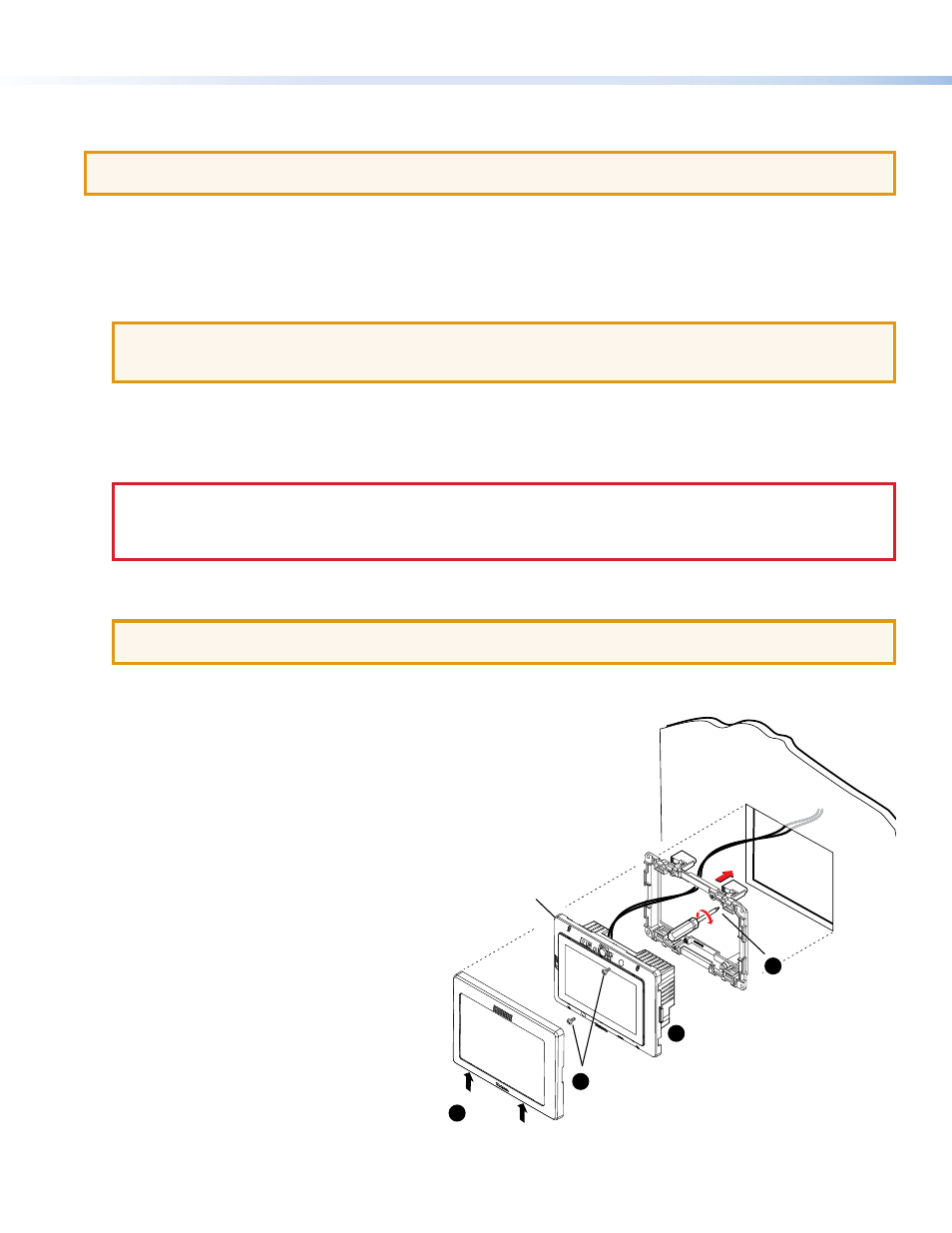
5.
Use a Phillips head screwdriver to tighten the locking arm screws of the wallplate adapter (see figure 1,
5
). As the screws
tighten, the locking arms rotate behind the wall and hold the adapter in place.
ATTENTION:
Do not overtighten the screws as this can damage the catches or the wall.
ATTENTION:
Ne serrez pas trop les vis au risque d’endommager les attaches ou le mur.
6.
Run the cables inside the wall to the hole, leaving enough slack in the cables to connect them to the back of the touchpanel.
7.
Plug the cables into the
z
If required, connect the digital input monitoring port.
z
Connect the LAN port to the PoE power injector or a PoE enabled switch.
z
If you use the LAN port only as a network connection, connect a 12 VDC,
1.0 A power supply to the 2‑pole captive screw power input connector.
8.
Push excess cables into the wall cavity.
9.
Press the touchpanel onto the wall plate adapter
(
¢
). Four catches, two on each side, hold the
touchpanel in place.
10.
Remove the bezel by inserting the provided Extron
pry tool into the notches on the bottom surface
of the bezel (
£
). The notches are on the bottom
surface of both the landscape and portrait bezels.
11.
Attach the touchpanel to the wall plate adapter
with the two Phillips head screws (#4‑40 x ¼”) that
are provided with the touchpanel (
¤
). For extra
security, these screws can be replaced with two
security screws of the same size (not provided).
12.
Replace the bezel by pressing the catches on the
faceplate into the corresponding slots on the front
of the touchpanel.
13.
If required, perform the initial configuration, using
the
(see page 4).
Figure 1.
Mounting the TLP Pro 520M
TLP Pro 520M snaps
to wallplate adapter
(2 places on each side).
Tighten screws to
rotate locking arms
and secure wallplate
adapter.
TLP Pro 520M
Mounting
Screws (2)
Remove
Bezel.
5
12
11
10