Pvm 220 • installation guide (continued) – Extron Electronics PVM 220 Installation User Manual
Page 4
4
PVM 220 • Installation Guide (Continued)
21.5"
(54.6 cm)
22.0"
(55.9 cm)
Cut the ceiling tile to 22 x 21.5 inches
and use that part for insertion into the
access door
.
Example: 24 x 24 inch Ceiling Tile
Bottom of Door (Door Locks)
Step 5 — Run signal and control cables to the PVM 220.
Run the signal and control cables either into cable clamps or through
conduit attached to the PVM 220 enclosure (see figure 7).
To install a cable clamp on the enclosure:
a.
Select a suitable sized cable clamp for the quantity and
thickness of cable to be fed into the enclosure. See the note
on page 3, Step 4 for knockout sizes.
b.
Identify the most suitable cable entry point and remove one
or more knockouts as needed.
NOTE: Remove only the knockouts that are to be used
for cabling. Leave intact the unused knockouts.
c.
Remove the large nut from the back of the cable clamp and
insert the clamp into the enclosure knockout from the inside.
d.
Place the nut on the clamp and tighten to secure.
e.
Pass the cables through the clamp into the enclosure. Leave
enough cable slack at the PVM 220 to ensure cable connection
to any device is maintained when the access door is open.
f.
Tighten down the cable clamp until the cables are held firmly.
Avoid damaging or bending cables at too sharp an angle.
NOTE: See the PoleVault System Installation Guide for
full cable connection details.
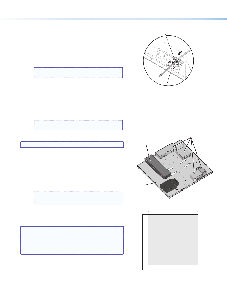
Step 6 — Install devices onto the device mounting plate.
NOTE: The maximum door load is 15 lbs (6.8 kg).
To mount the devices and accessories:
a.
Carefully align the switcher with the appropriate holes in the
marked location (indicated by arrows on the mounting plate).
b.
Secure the switcher with the supplied #4-40 » inch mounting
screws, tightening each one until snug. Do not overtighten.
c.
Mount the power supply onto the device mounting plate in the
marked location (indicated by arrows on the mounting plate), using
the supplied screws.
NOTE: Replacement power supplies must be either the
equivalent Extron power supply, or a UL Listed NEC
Class 2 power supply.
d.
Mount any other devices following the procedures in the
supplied device guide.
Step 7 — Cut and install the ceiling tile in the access door.
NOTES:
•
The door can accept a ceiling tile thicknesses of
Œ
-1… inches. Check the tile thickness before cutting.
•
If the ceiling tiles have a specific pattern direction, ensure
the overall pattern direction is maintained when cutting
and fitting the cut tile insert into the access door.
a.
Mark the dimensions (22 inches by 21.5 inches) for the PVM 220
access door on the installation tile and cut the tile to size.
b.
With the access door open, insert the cut ceiling tile into the
door frame (see figure 10, on page 5).
PVS
405
SA I
P
PO
LEV
AUL
T S
WIT
CH
ER
INP
UTS
AUD
IO LE
VEL
ADJ
UST
PAGI
NG
SEN
SOR
SENS
ITIV
ITY
PEA
K
NO
RM
AL
SIG
NAL
VOIC
ELIFT
PEA
K
NO
RM
AL
SIG
NAL
INP
UT
SELE
CT
CON
FIG
R
1
2
3
4
5
AUX
AUDI
O
E
Mount the PoleVault
switcher with the front
panel facing outwards
in the marked location.
Mount other optional
devices as desired.
PoleVault Switcher
Power Supply
Device
Mounting Plate
Figure 8.
Install the devices onto the mounting plate.
Figure 9.
Cut the ceiling tile for insertion into the
access door.
1. Push the cable clamp into the
knockout from inside the enclosure.
2. Attach the nut from the outside
of the enclosure.
Figure 7.
Install a cable clamp on the PVM 220
enclosure (viewed from above).