Pvm 220 • installation guide (continued), Installation – Extron Electronics PVM 220 Installation User Manual
Page 2
PVM 220 • Installation Guide (Continued)
2
Installation
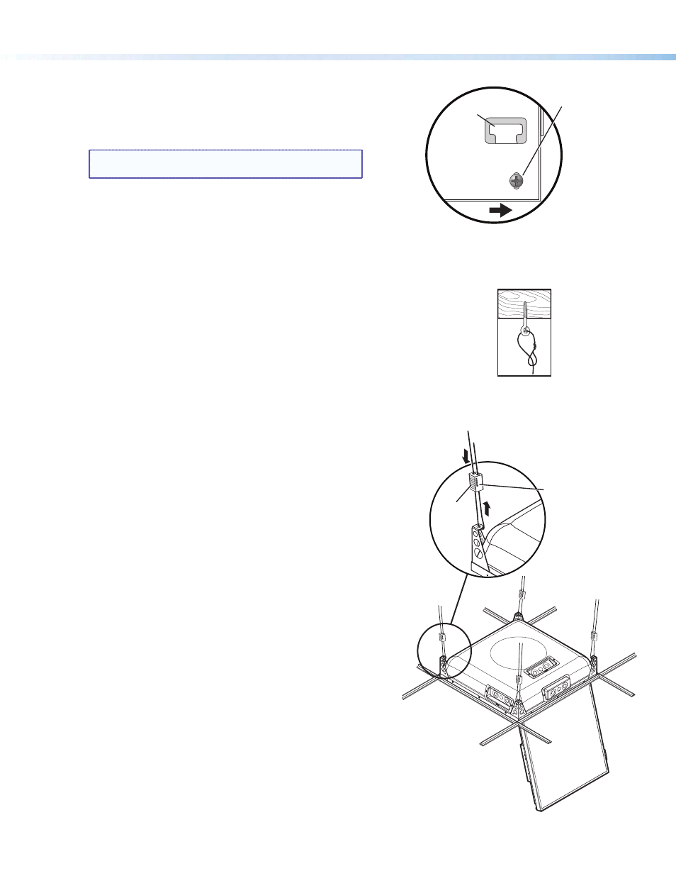
Step 1 — Remove device mounting plate from the access door.
a.
Open the access door and unscrew the two Phillips screws that are
located in the bottom corners of the plate (left and right sides), near
the door latches and door tether "T."
NOTE: Do not remove any of the screws located below
the hinges.
b.
Swing the bottom of the plate up to separate it from the door frame,
then slide the plate to the right until it becomes free of the hinge pins
on the door frame.
Retain the device mounting plate for later use (see step 6).
Step 2 — Remove ceiling tile and install suspension cables.
For threaded rod installation see step 3, threaded rod section on next page.
a.
At the location where the PVM 220 is to be installed, remove the ceiling
tile and mark the T-grid for that tile then remove the adjacent tiles to make
working on the grid easier.
b.
At an approximate angle of 10 degrees out from each corner of where the
PVM 220 will be installed, mark and drill four holes in the structural
ceiling for the suspension cable anchors.
c.
Screw a lag eye bolt (or an appropriate anchor) into each hole.
d.
Thread the looped end of the suspension cable though the bolt eyehole,
pass the rest of the cable through the loop and tighten.
Allow each cable to hang down.
Step 3 —Suspend the main PVM 220 enclosure from the ceiling.
a.
Lift and place the PVM 220 enclosure carefully onto the T-grid so
that it sits squarely on the grid.
b.
Holding a cable lock, press the locking pin down (following arrow
directions) and pass the loose end of one the cables down through
the large hole in the lock.
Continue to push the cable down until about 12-15 inches of cable
has exited the lock.
c.
Pass the loose end of the cable directly through the corner hole on
the PVM 220 enclosure and then back up through the other large hole
in the lock.
Pass at least six inches of cable out through the top of the lock.
d.
Repeat for each corner.
e.
Adjust the cable tension through all locks, making each cable taut
without lifting the PVM 220 off the T-grid.
Thread the cable down through the cable
lock, through the hole on the frame of the
enclosure and back up through the lock.
Cable Lock
Locking Pin
Figure 2.
Remove the mounting plate from
the door.
Figure 3.
Tie the cable to the ceiling anchor.
a. Remove this screw on
the right and left sides
of the mounting plate.
b. Swing the mounting plate out from the door frame
and slide the plate to the right, off the hinge pins.
Bottom of Door
(inside right
corner view)
Door Tether “T”
Figure 4.
Secure the PVM 220 to the ceiling
with cable on all corners.