E-peak switch positions (see, Item – Extron Electronics MTP 15HD RS Series User Guide Rev. F User Manual
Page 14
d
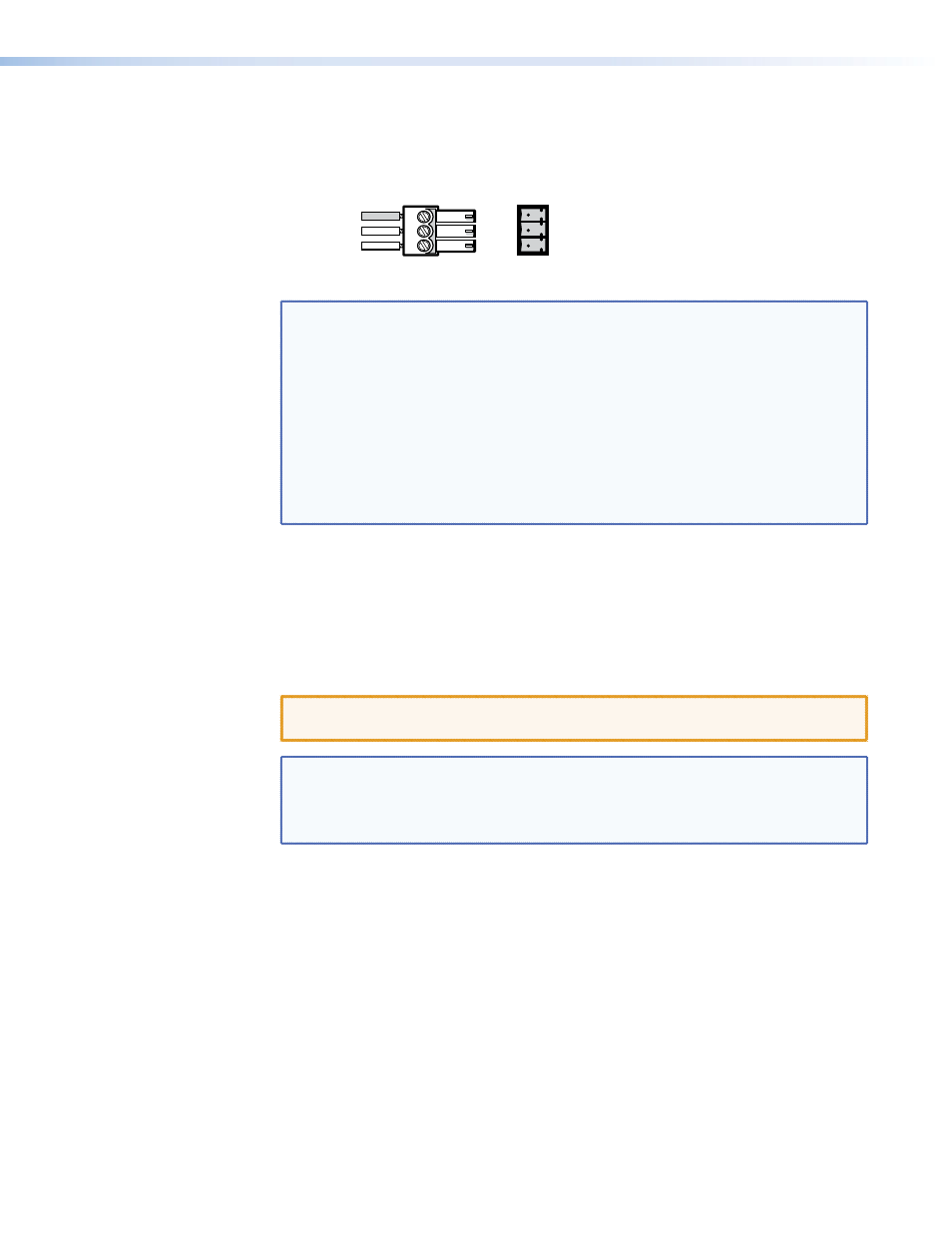
RS-232 connector — Connect a serial communications port to this 3.5 mm, 3-pole
captive screw connector for bidirectional RS-232 communication. Wire the connector as
shown in figure 6.
Ground
Tx
Rx
Gnd
Receive
Transmit
Connected RS-232
Device Pins
MTP
Pins
Figure 6.
RS-232 Connector Wiring
NOTES:
•
By default, the RS-232 portion of the TP link is unidirectional only from
the transmitter to the receiver. If there is only one receiver in a system,
a jumper within the receiver allows the RS-232 communication to be
bidirectional (see "
" on page 5).
•
The length of the exposed wires in the stripping process is critical. The
ideal length is 3/16 inches (5 mm). If the exposed section is longer, the
exposed wires may touch, causing a short circuit between them. If it is
shorter, the wires can be easily pulled out, even if tightly fastened by the
captive screws.
•
Do not tin the wires. Tinned wire does not hold its shape and can
become loose over time.
e
Pre-Peak switch — The Pre-Peak switch alters the TP signal output to correct for
on page 4 for suggested switch settings based on the
transmitted video format and transmission distance.
f
Output connector — Connect one end of a TP cable to this RJ-45 female connector
on the transmitter. Connect the free end of the same TP cable to the RJ-45 female
connector on the receiver. See "
Twisted Pair Cable Termination
the RJ-45 connectors.
CAUTION: Do not connect these devices to a computer data or
telecommunications network.
NOTES:
•
The non-C7 transmitters and receivers will not work properly with
STP201 or CAT 7 STP cable.
•
The C7 transmitters and receivers will work properly only with STP201
or CAT 7 STP cable.
MTP 15HD RS Series • Installation and Operation
10