Transmitter rear panel features, Connect the transmitter inputs (see, Transmitter rear panel – Extron Electronics MTP 15HD RS Series User Guide Rev. F User Manual
Page 13: Features
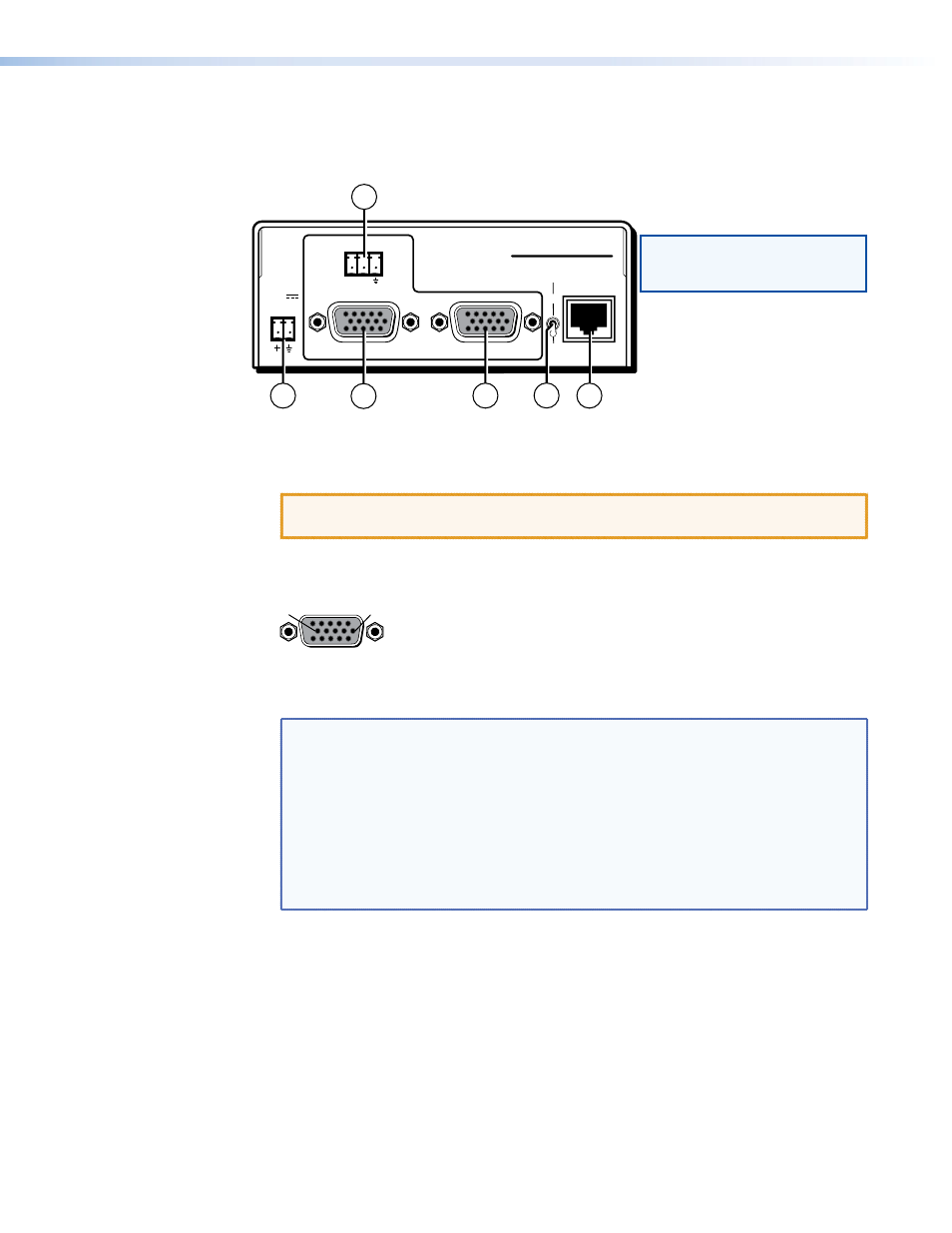
Transmitter Rear Panel Features
Figure 4 shows an MTP T 15HD RS transmitter, which has all of the connectors and other
features that are on either transmitter in the MTP 15HD RS series.
OUTPUT
INPUT
POWER
12V
.5A MAX
Tx Rx
RS-232
MONITOR
PRE-PEAK
ON
OFF
MTP T 15HD RS
NOTE: A “C7” label is affixed to
transmitters designed for
STP201 or CAT 7 cable.
4
1
2
3
5
6
Figure 4.
Transmitter Rear Panel
a
Power connector — Plug the included external 12 VDC power supply into this 2-pole
captive screw connector. Wire the connector as shown in
on page 13.
CAUTION: Read the notes, cautions, and warnings in the "
" section on page 13 before wiring the connector.
b
Input video connector — Connect a computer video source to this 15-pin HD
connector for high resolution video input (see figure 5).
5
1
15
11
6
10
Female
Figure 5.
15-pin HD Connector
NOTES:
•
Input only sync signals (no video signals) on the sync pins (13 and 14).
•
For component video, use the R (R-Y) and R return pins (pins 1 and 6),
G (Y) and G return pins (pins 2 and 7), and B (B-Y) and B return pins
(pins 3 and 8).
•
For S-video, use the R, R return (C-chroma), G, and G return (Y-luma)
pins.
•
For composite video, use the G pin and the associated return pin. For
additional genlocked video signals, use the R, B, and associated return
pins.
c
Monitor connector — Connect a video monitor to this 15-pin HD connector for
buffered, high resolution video loop-through.
MTP 15HD RS Series • Installation and Operation
9