Installing bme(s), Matrix 3200/6400 system installation – Extron Electronics Matrix 3200 Series User Guide User Manual
Page 17
Extron • Matrix 3200/6400 Series • User’s Manual
Chapter 2 • Installing the Matrix 3200/6400 Wideband Video Switchers
Matrix 3200 & 6400 Wideband Video/Sync System Installation
Extron recommends that the following steps be done in the order listed to install
a Matrix 3200 & 6400 Wideband Video/Sync System.
1. Installing BME(s). (Page 2-1)
2. Set the BME address numbers (0 - 5). (Page 2-2)
3. Connect the BME COMM interconnecting cable(s). (Page 2-2)
4. Connect the RS-232/RS-422 cable to BME #0’s serial port. (Page 2-2)
5. Connect the AC Power cable(s) to the BME(s). (Page 2-2)
6. Apply AC power to the BMEs and Verify Normal Power-Up. (Page 2-2)
7. Load the Matrix 3200/6400 System Virtualization/Control Software. (Page 2-3)
8. Virtualize the system if required. (Page 3-1)
9. Connecting cables to BMEs (video, sync and/or audio cables). (Page 2-5)
The numbered procedures that follow match the steps above.
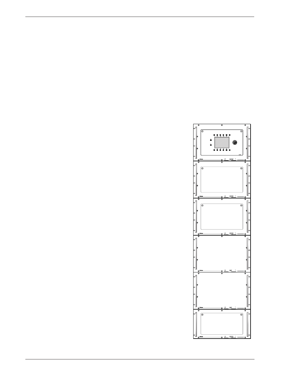
1. Installing BME(s)
BMEs may be separated by up to 12 feet and
rack mounting is NOT required. If the BMEs are
to be rack mounted, they may mounted in any
order within a rack or cabinet. The limiting factor
is the BME COMM interconnecting cable length
which is 12 feet maximum. There are no
restrictions to the order in which BMEs may be
mounted relative to each other. Logically, the
BME addresses in a system such as the one
shown in Figure 2-1.A would be set to 0 - 5
sequentially from top to bottom, however, a
different order is acceptable and will not impact
system operation in any way.
The location of the equipment within a room
should be given careful consideration. Poor
planning, with the number of cables involved,
could result in a cluttered appearance. Power
requirements and the amount of heat exhaust
from the system should be taken into
consideration.
The following restrictions apply to installing
BMEs.
•
One BME must be assigned as BME #0.
•
BME #0 cannot be a Sync module.
•
Address assignments must not skip numbers.
•
Address assignments of 0 - 5 are accepted,
BMEs w/address 6-9 are ignored.
•
A system is limited to one audio module.
•
A system may NOT include both Wideband
video and Low Resolution video modules.
2-1
MATRIX 6400
WIDEBAND VIDEO
MATRIX 6400
WIDEBAND VIDEO
MATRIX 6400
WIDEBAND VIDEO
MATRIX 6400
SYNC
MATRIX 6400
SYNC
MATRIX 6400
WIDEBAND VIDEO
POWER SUPPLIES
COMMUNICATIONS
PRIMARY
RGB
MUTE
AUDIO
MUTE
TX
RS232
BME
REMOTE
SYSTEM
STATUS
REDUNDANT
RX
DIAGNOSTICS
+V
-V
POWER SUPPLIES
COMMUNICATIONS
PRIMARY
TX
RS232
BME
REMOTE
SYSTEM
STATUS
REDUNDANT
RX
DIAGNOSTICS
+V
-V
POWER SUPPLIES
COMMUNICATIONS
PRIMARY
TX
RS232
BME
REMOTE
SYSTEM
STATUS
REDUNDANT
RX
DIAGNOSTICS
+V
-V
POWER SUPPLIES
COMMUNICATIONS
PRIMARY
TX
RS232
BME
SYSTEM
STATUS
REDUNDANT
RX
DIAGNOSTICS
+V
-V
POWER SUPPLIES
COMMUNICATIONS
PRIMARY
TX
RS232
BME
SYSTEM
STATUS
REDUNDANT
RX
DIAGNOSTICS
+V
-V
POWER SUPPLIES
COMMUNICATIONS
PRIMARY
TX
RS232
BME
REMOTE
SYSTEM
STATUS
REDUNDANT
RX
DIAGNOSTICS
+V
-V
FPC-1000
Figure 2-1.A Rack-mounted Matrix 6400 System with RGBHV
video plus audio support.