Connecting the input source, Connecting the output displays, Connecting output displays – Extron Electronics HDMI DA6 User Guide User Manual
Page 11: Connect the display devices, Input device
connecting the Input Source
Use a HDMI cable to connect the input source to the female HDMI socket on the rear panel
(
b
in figure 2).
The connectors are fully HDCP compliant. With cables up to 25 feet (7.6 m) they support
resolutions of up to 1080p @ 60 Hz with 12‑bit color. With cables up to 50 feet (15.2 m) they
support 1080p or 1920x1200 @ 60 Hz with 8‑bit color.
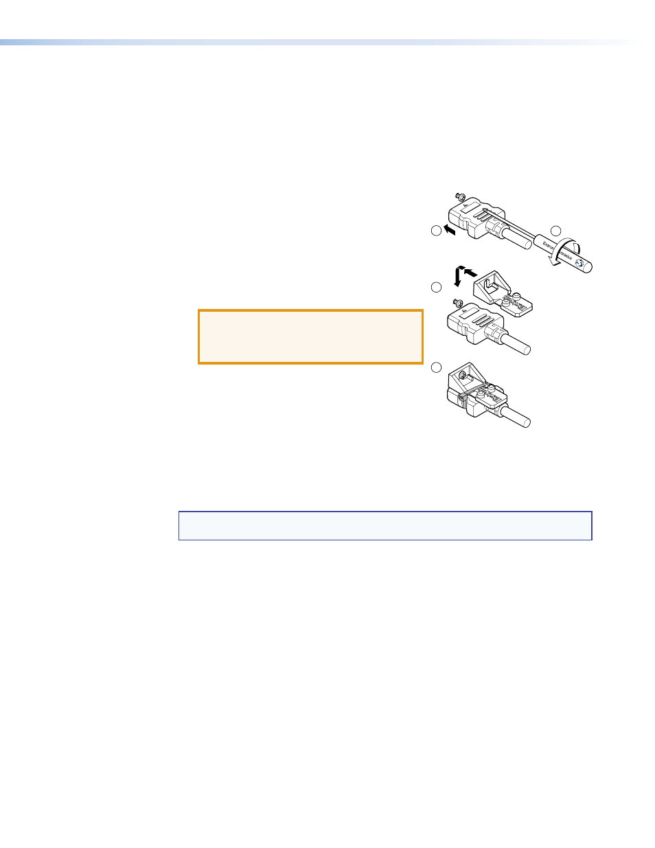
Follow these instructions to secure the input and output HDMI connectors to the unit with the
LockIt
™
HDMI lacing bracket provided:
1.
Plug the HDMI cable into the panel connection.
2.
Loosen the HDMI connection mounting screw from
the panel enough to allow the LockIt lacing bracket
to be placed over it. The screw does not have to be
removed.
3.
Place the LockIt lacing bracket on the screw and
against the HDMI connector, then tighten the screw
to secure the bracket.
ATTENTION:
Do not overtighten the HDMI
connection mounting screw. The shield it
fastens to is very thin and can easily be
stripped.
4.
Loosely place the included tie wrap around the
HDMI connector and the LockIt lacing bracket as
shown.
5.
While holding the connector securely against the lacing
bracket, tighten the tie wrap, then remove any excess length.
connecting the Output Displays
Use a HDMI cable to connect up to four (HDMI DA4) or six (HDMI DA6) output displays to the
female HDMI sockets on the rear panel (
c
NOTE:
Secure the input and output HDMI connectors to the distribution amplifier with the
provided LockIt
™
HDMI lacing bracket (see
Connect the primary display to output 1 since, by default, EDID from output 1 is read and
stored automatically. 48 factory loaded EDIDs are available. Alternatively, you may store and
use EDID from one of the other display devices connected to the distribution amplifier. For
more information, see EDID Minder on page 11 or SIS Commands on page 15.
The HDMI DA4 and HDMI DA6 monitor the EDID of each connected display to ensure they are
compatible with the current input signal. If necessary, the following adjustments are made for
each output independently:
z
Interface format: If the connected display is DVI and the input signal is HDMI, the signal
is reformatted to DVI. If the output is HDMI and the input is DVI, no reformatting is needed
because HDMI is backwards compatible with DVI.
z
Video color bit depth: If the connected output device does not support the color
bit depth of the input signal, it is truncated down to the next level that is supported
(12‑bit > 10‑bit > 8‑bit). The signal can be forced to always truncate to 8‑bit via SIS
commands, disabling deep color.
All outputs carry +5 VDC and up to 250 mA on pin 18, regulated by a current limiting circuit.
3
4
3
1
2
HDMI DA4 and HDMI DA6 • Installation
5