Set (tie) connection commands – Extron Electronics Matrix 100 Switcher User Manual
Page 54
Extron • Matrix 100 • User’s Manual
Appendix A • RS-232 Matrix Programmer’s Guide
Set (Tie) Connection Commands
The Set Connection Commands that follow are the programming equivalent of
the Tie Menus used from the QS-FPC.
Planes and Plane Maps
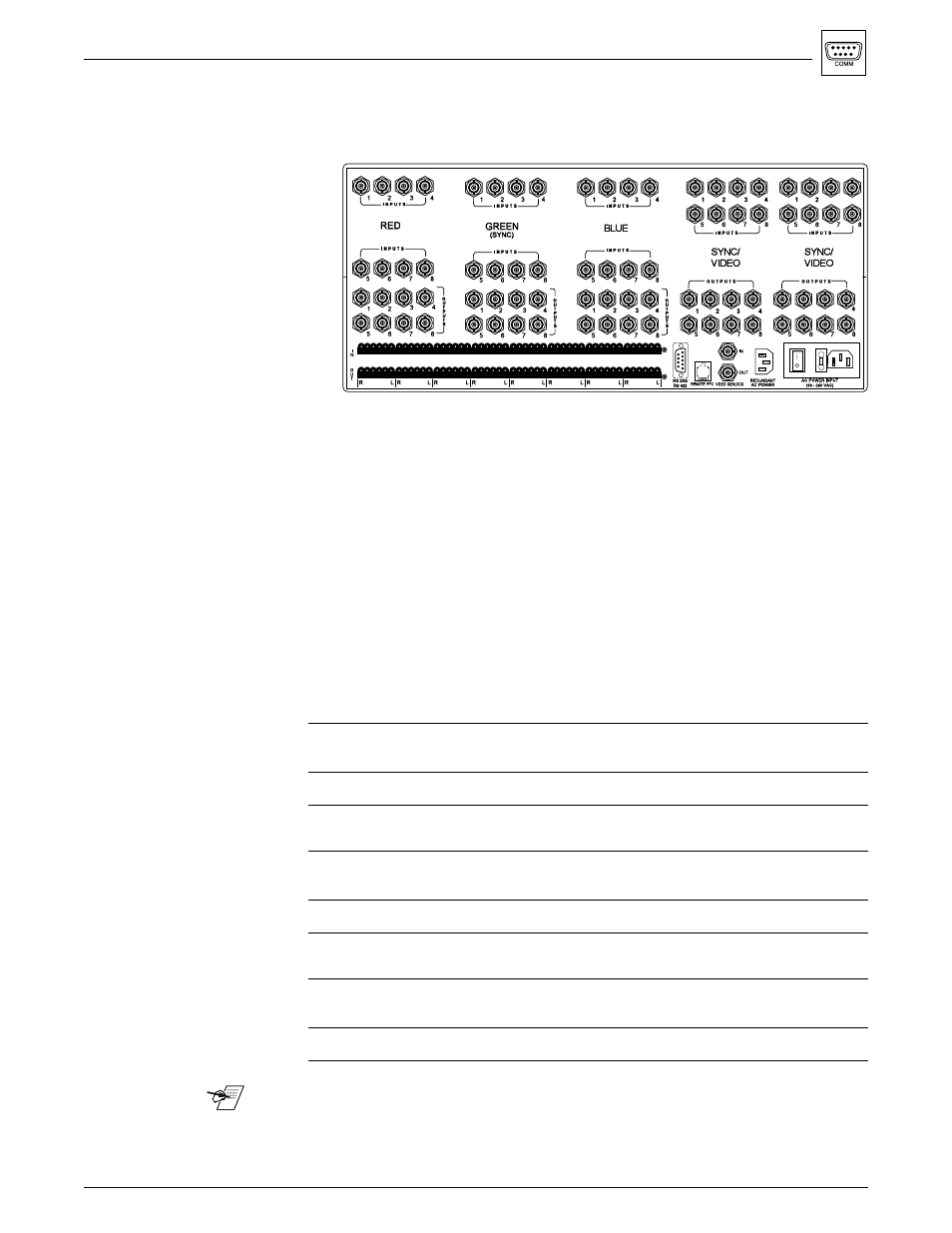
When looking at the rear panel of the Matrix 100, the planes are counted from
left-to-right, top-to-bottom. Presently, six planes (switching modules) are
supported with hardware. Planes 1, 2, and 3 are reserved for Red, Green, and
Blue modules. Planes 4 and 5 can have either sync or video switching modules,
depending on how the Matrix 100 was configured at the factory. A Matrix, built
with both a sync and composite video switcher, will have the sync module in
plane 4 and the composite video module in plane 5. Plane 6 is reserved for
stereo audio.
The Matrix 100 can access the planes independently, or in combinations, or
groups. Commands can access the planes, by using Plane Map bytes, called
PlnMap0 and PlnMap1. (PlnMap1 is not used at this time.)
Examples below show the correlation between the planes and the bit numbers.
PlnMap0 to access the RGBS Switcher (planes 1, 2, 3 & 4)
Plane #
n/a
7
6
5
4
3
2
1
Plane Use
n/a
Audio
Audio
Sync/
Sync/
Blue
Green
Red
#2
#1
Video
Video MRAM MRAM MRAM
PlnMap Bit #
7
6
5
4
3
2
1
0
8F hex
1
0
0
0
1
1
1
1
PlnMap0 to access the Composite Video Switcher (plane 5)
Plane #
n/a
7
6
5
4
3
2
1
Plane Use
n/a
Audio
Audio
Sync/
Sync/
Blue
Green
Red
#2
#1
Video
Video MRAM MRAM MRAM
PlnMap Bit #
7
6
5
4
3
2
1
0
90 hex
1
0
0
1
0
0
0
0
PlnMap0 to access the Audio Switcher (plane 6)
Plane #
n/a
7
6
5
4
3
2
1
Plane Use
n/a
Audio
Audio
Sync/
Sync/
Blue
Green
Red
#2
#1
Video
Video MRAM MRAM MRAM
PlnMap Bit #
7
6
5
4
3
2
1
0
A0 hex
1
0
1
0
0
0
0
0
______ The plane number refers to the physical address of the I/O module.
A-8
1
2
3
4
3