Iec power panel – Extron Electronics Matrix 100 Switcher User Manual
Page 31
Extron • Matrix 100 • User’s Manual
Chapter 4 • Matrix 100 Hardware Installation
This chapter covers only the installation of the Matrix 100 hardware. Connecting
its inputs and outputs is covered in Chapter 3 and setup is Chapter 4.
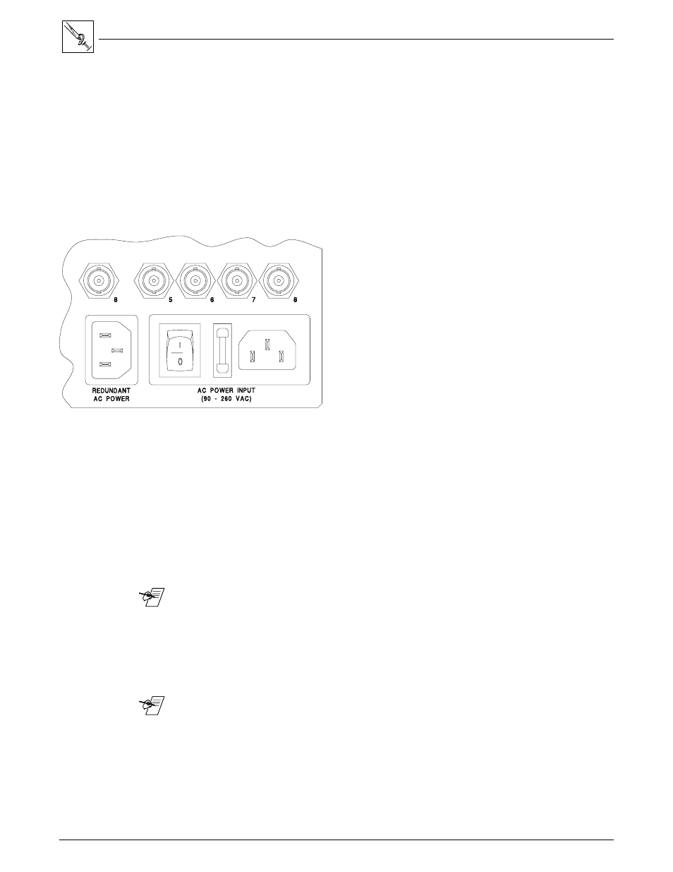
IEC Power Panel
The IEC Power Panel consists of an On/Off switch, a fuse cover and two male
power connectors. (See Figure 4-1.) The second connector is provided for a
Redundant power supply.
Standard Power Supply
The Matrix 100 Series switcher/router has an auto-switching power supply that
operates from any input voltage from 90 to 260 VAC, 50/60 Hz. No equipment
changes are necessary.
Fuse
Fuse Type = 5mm x 20mm
Fuse Rating = 240V, 0.8A Super Slo Blo
Power Switch
Power Switch -
1 = On
0 = Off
Figure 4-1. IEC Power Panel: Power Switch, Fuse and Power Connectors
Redundant Power Supply (optional)
To improve equipment reliability in critical applications, the Matrix 100 can be
configured with a redundant internal power supply. With this option, the
Matrix 100 will automatically switch to the backup supply if the primary supply
fails. If the Matrix 100 switches to the backup power supply, it continues to
operate without interruption, and sends a command to the Host system to
indicate a change in status. If the Matrix has a QuickSwitch Front Panel
Controller, the Power LED will flash to alert the user that a power failure has
occurred.
_______ To install this optional power supply, see procedure on page 4-5.
QuickSwitch Front Panel Controller
The QuickSwitch Front Panel Controller (QS-FPC) provides local control of all
Matrix 100 functions. This optional feature is intended to supplement normal
RS-232 computer control with a local or remote operator control.
_______ The following pages include procedures for panel installation.
4-1