Audio terminal connections – Extron Electronics Matrix 100 Switcher User Manual
Page 23
Chapter 2 • Rear Panel Connections
Extron • Matrix 100 • User’s Manual
Tip
Sleeve
Ring (-)
Tip (+)
Sleeve
Ring (-)
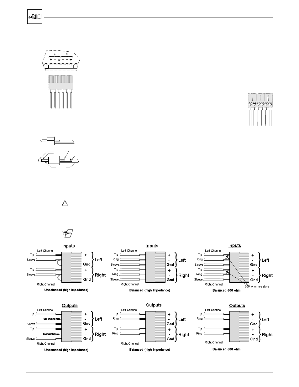
Audio Terminal Connections
The rear of the Matrix 100 has two rows (16 sets) of audio connector pins, below
the BNC connectors. The top row is for 8 inputs, and the bottom for 8 outputs.
Each group of six pins accommodates a left and a right audio channel. One
sample is shown here.
The 6-terminal audio connectors are supplied with the switcher. The connectors
are wired to the audio cables, using the captive screws inside the connectors.
The connectors are then plugged into the appropriate position in the audio
terminal strip on the rear panel. The audio area of the back panel is labeled "R"
(right) and "L" (left) for each channel.
When wiring the connectors and inserting them into the Matrix 100
switcher, the screw heads (see illustration right) must face down.
Figure 2-8. Audio Connectors with Captive Screws (above and right)
Audio Wiring Applications
Three methods of wiring the connectors for input and output are listed here, and
illustrated below. The connector screws do not show in the picture because they
are on the other side.
·
Unbalanced High Impedance (High Z) Stereo Tip, Ring, Ground (Left & Right)
·
Balanced High Impedance (High Z) Stereo Tip, Ring (Left & Right)
·
Balanced 600 ý input Impedance Stereo Tip, Ring (Left & Right)
Figure 2-9. Typical Audio Cable Connectors
_________ If using unbalanced audio output, use lower-left connector as an example, and
connect the sleeve to Gnd. Connecting it to the negative (-) terminal will damage
audio output circuits.
_______ Use captive-screw audio connectors, Extron part number 10-163-01
Figure 2-10. Three ways to wire the Input and Output Audio Connectors
2-9