Installation – Extron Electronics HFX 100 Rx User Manual
Page 4
4
HFX 100 Tx and HFX 100 Rx • User Guide
c
Optical output connector — Connect one end of one multimode fiber optic cable (not provided) into this LC connector. The
other end connects into the LC input connector on the HFX 100 Rx. The cable can be up to 300 meters (984 feet) in length.
CAUTION:
•
Possible damage to eyesight. The HFX 100 Tx outputs continuous laser (Class 1 rated), which may be harmful
and dangerous to the eyes; use with caution. Do not look into the rear panel fiber optic cable connector or into the fiber
optic cable itself. Plug the attached dust cap into the optical transceiver when the fiber optic cable is unplugged.
•
Possible radiation exposure. Use of controls or adjustments or performance of procedures other than those
specified herein may result in hazardous radiation exposure.
HFX 100 Rx Rear Panel
POWER
12V
- - A MAX
INPUT
OUTPUT
HFX 100 Rx
POWER
12V
- - A MAX
INPUT
OUTPUT
HFX 100 Rx
3 feet (0.91 m) HDMI cable
a
c
b
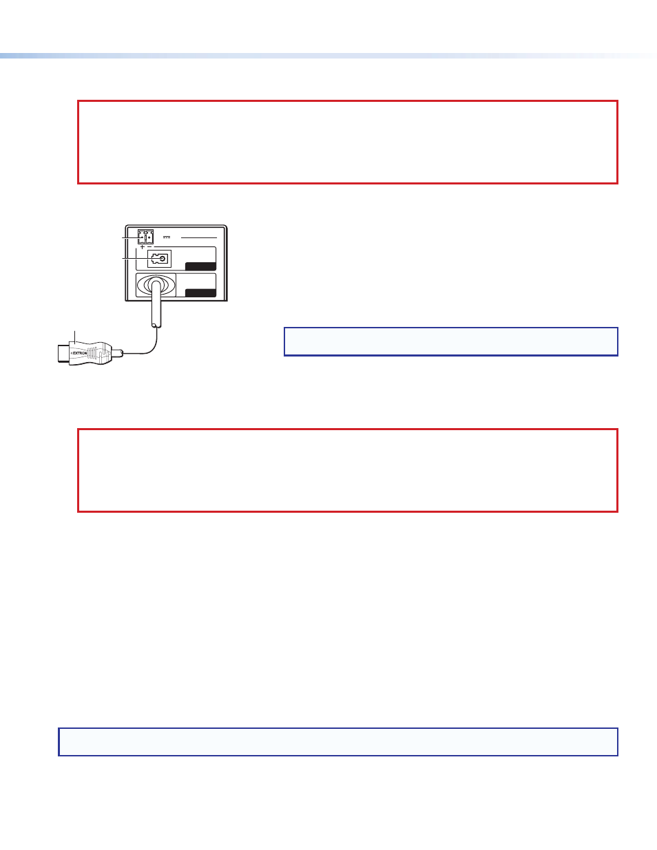
Figure 5.
HFX 100 Rx Rear Panel
c
Optical input connector — Connect one end of the multimode fiber optic cable (not provided) into this LC connector. The other
end connects into the LC output connector on the HFX 100 Tx.
CAUTION:
•
Possible damage to eyesight. The HFX 100 Tx outputs continuous laser (Class 1 rated), which may be harmful
and dangerous to the eyes; use with caution. Do not look into the rear panel fiber optic cable connector or into the fiber
optic cable itself. Plug the attached dust cap into the optical transceiver when the fiber optic cable is unplugged.
•
Possible radiation exposure. Use of controls or adjustments or performance of procedures other than those
specified herein may result in hazardous radiation exposure.
When the HFX 100 Rx is receiving optical input, the front panel LED lights green.
Installation
To install the HFX 100 extender, follow these instructions:
1.
Mount the HFX 100 Tx and HFX 100 Rx
in suitable locations (see page 5).
2.
Connect the provided power supply to the HFX 100 Tx
(see page 3). The front panel LED lights amber.
3.
Connect the provided power supply to the HFX 100 Rx. The front panel LED lights amber.
4.
Connect the transmitter and receiver using a multimode fiber optic cable.
5.
Connect the HDMI display device to the HFX 100 Rx. Do not power on the display at this time.
6.
Connect the HDMI source device to the HFX 100 Tx
(see page 3). Do not power on the source at this time.
7.
Power on the display device.
8.
Power on the source device.
NOTE:
The display device must be powered on before the source device to allow correct DDC communication between the
display and the source while the source device is booting up.
When the HFX 100 Tx is receiving HDMI input, the front panel lights green.
When the HFX 100 Rx is receiving an optical input, the front panel lights green.
a
12 VDC power input — Connect the provided 12 VDC power supply to the
back panel captive screw connectors. When power is provided to the unit but
there is no HDMI input, the front panel lights amber.
See figure 5 and the
connecting the power supply.
b
HDMI output connector — Connect a HDMI display device to this male
connector.
NOTE:
With appropriate HDMI to DVI-D cables or adapters, the unit will
output an DVI signal.