Extron, Extron a, Panels and cables – Extron Electronics HFX 100 Rx User Manual
Page 3: A c b, Front panel, Hfx 100 tx rear panel
3
HFX 100 Tx and HFX 100 Rx • User Guide
Panels and Cables
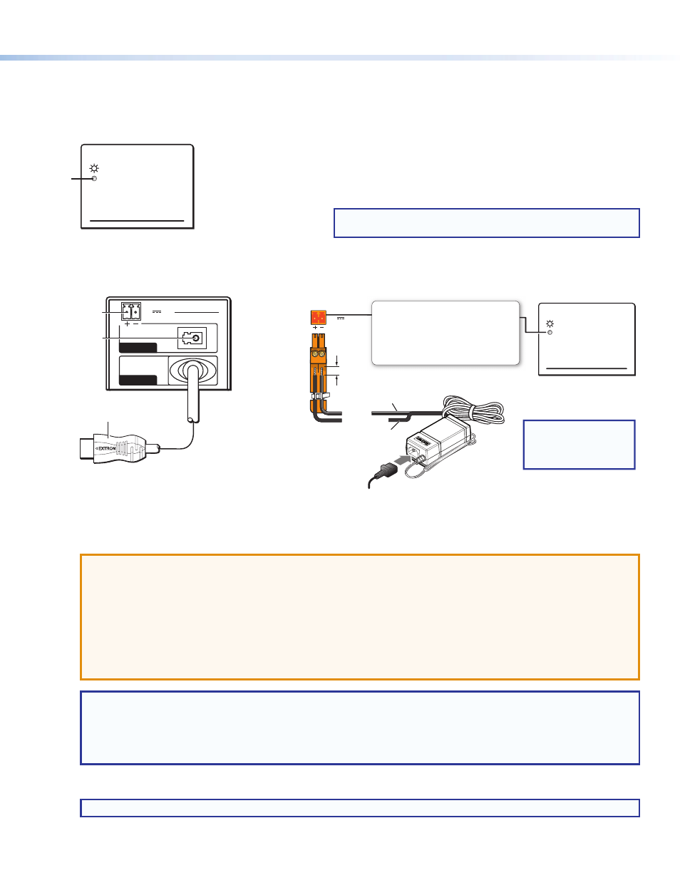
Front Panel
Both the transmitter and receiver have identical front panels.
Extron
Extron
a
Figure 2.
HFX 100 Tx and HFX 100 Rx Front Panel
HFX 100 Tx Rear Panel
POWER
12V
1.0 A MAX
OUTPUT
INPUT
HFX 100 Tx
POWER
12V
1.0 A MAX
OUTPUT
INPUT
HFX 100 Tx
3 feet (0.91 m) HDMI cable
a
c
b
Figure 3.
HFX 100 Tx Rear Panel
POWER
12V
1.0 A MAX
Extron
Extron
Ground
all devices.
External
Power Supply
(12 VDC, 1 A max.)
– Return
+12 VDC input
1A MA
X
100-240V 50-60Hz
Ridged, –
Smooth, +
3/16"
(5 mm)
Max.
Rear Panel
Front Panel
NOTE:
Check the polarity
of the power supply
before connecting it
to the unit.
Power Input
Connect to an
Extron 12 VDC,
1 A power
supply.
The front panel LED lights:
• Amber when receiving
power only
• Green when receiving
power and an active
HDMI signal
Figure 4.
12 VDC, 1A Power Input
a
12 VDC power input — Connect the provided 12 VDC, 1A power supply to the rear panel captive screw connector (see figure 4).
When power is provided to the unit but there is no HDMI input, the front panel lights amber.
ATTENTION:
•
Always use a power supply provided by or specified by Extron. Use of an unauthorized power supply voids all
regulatory compliance certification and may cause damage to the supply and the end product.
•
Unless otherwise stated, the AC/DC adapters are not suitable for use in air handling spaces or in wall cavities. The
power supply is to be located within the same vicinity as the Extron AV processing equipment in an ordinary location,
Pollution Degree 2, secured to the equipment rack within the dedicated closet, podium, or desk.
•
The installation must always be in accordance with the applicable provisions of National Electrical Code ANSI/NFPA 70,
article 725 and the Canadian Electrical Code part 1, section 16. The power supply shall not be permanently fixed to
building structure or similar structure.
NOTES:
•
The length of the exposed wires in the stripping process is critical. The ideal length is 3/16 inch (5 mm). If it is any
longer, the exposed wires may touch, causing a short circuit between them. If it is any shorter, the wires can be easily
pulled out even if tightly fastened by the captive screws.
•
Do not tin the wires. Tinned wire does not hold its shape and can become loose over time.
b
HDMI input connector — Connect a HDMI output to this male connector.
NOTE:
With appropriate DVI-D to HDMI cables or adapters, the unit will accept DVI-D input.
When the transmitter is receiving an HDMI input signal, the front panel LED lights green.
a
Front Panel LED — lights amber if the unit (transmitter or receiver) is
receiving power from the 12 VDC, 1A power supply. The transmitter
LED lights green if the unit is receiving a TMDS clock signal. The
receiver LED lights green if the unit is receiving an optical signal.
NOTE:
During initialization, the LED may need a few seconds to
stabilize to the correct state.