Removing the front panel connector, Replacing the lower enclosure connector, Figure 1-4 — disconnecting the interior ac cable – Extron Electronics RJ-11 Installation User Manual
Page 7: Figure 1-5 — removing the front panel, Figure 1-6 — releasing the bezel plug-in detent
RJ-45 to RJ-11 Conversion Kit • HSA 400, 402 Installation
RJ-45 to RJ-11 Conversion Kit • HSA 400, 402 Installation
HSA 400, 402, Installation, cont’d
1-7
1-6
Removing the Front Panel Connector
1
Through the access hole in the rear of the enclosure, cut
the tie wraps that bundle the power and CAT 6 cables.
2
.
Through the access hole in the rear of the enclosure,
disconnect the 3-prong cable connector on the interior AC
cable (figure 1-4).
Figure 1-4 — Disconnecting the interior AC cable
3
.
Open the top panel and remove and retain the four Allen
screws on the right and left sides of the front panel
(figure 1-5). Lift the front panel away from the enclosure
as far as the connected cables allow.
Remove two Allen
screws from each side.
Lift panel out
of enclosure.
125 -
50/6
0 Hz
5A
HSA 400
H. SH
IFT
COM
PUT
ER
INPU
T
SELE
CT
AUD
IO
RG
B 5
80xi
SI A
AP
Figure 1-5 — Removing the front panel
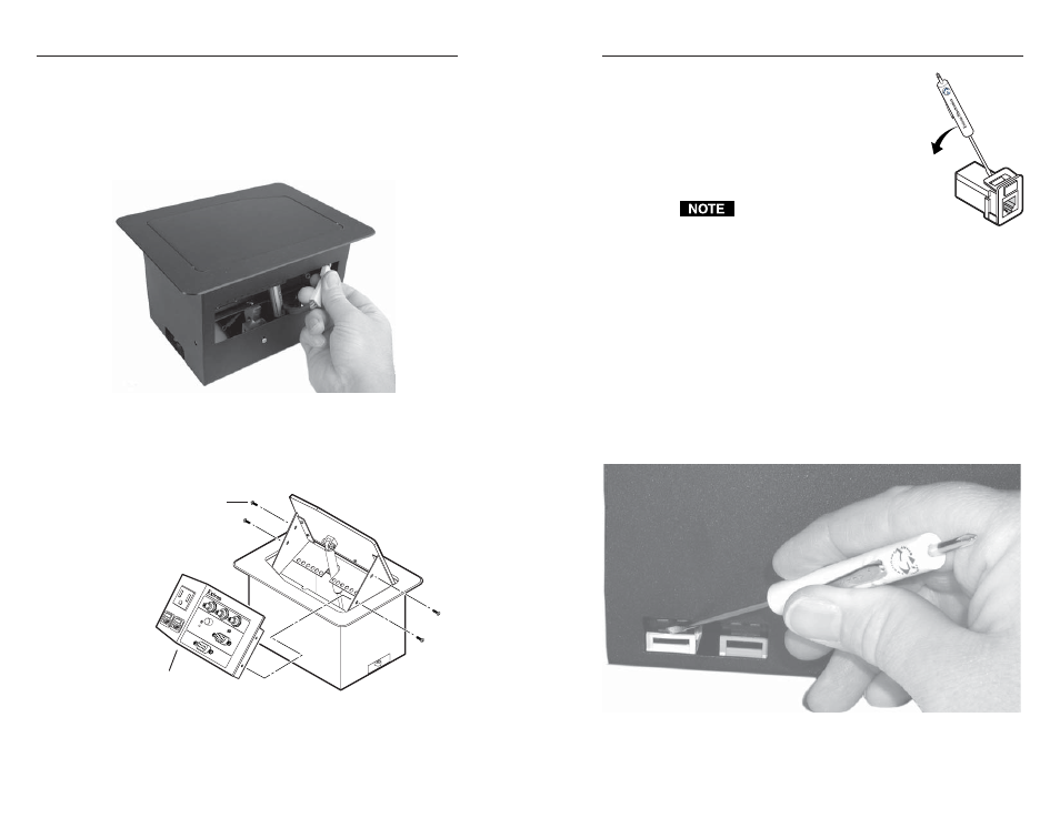
4
.
With a tweeker, push down on and
gently twist on the front of each RJ-45
connector detent to disconnect the
connector from the rear of the front panel
bezel plug-in.
5
.
Remove the front panel from the
enclosure. Leave the top panel open for
the time being.
Ensure that the edges of the front panel
do not scratch the finished surface of the top
panel flange when removing the panel.
Replacing the Lower Enclosure Connector
1
.
Identify the RJ-45 connector to be replaced, then
simultaneously
:
a
.
With a tweeker in one hand, reach through the small
access hole in the front of the enclosure (figure 1-6)
and gently pry outward on the front of the RJ-45
connector detent on the bezel plug-in,
b
.
While you reach your other hand through the access
hole in the rear of the enclosure and tilt the connector
back.
This disconnects the connector from the interior of the
lower enclosure without damaging the bezel plug-in.
Figure 1-6 — Releasing the bezel plug-in detent