Step 4 — run cables between units, Step 6 — power the units, Step 7 — final installation – Extron Electronics DTP T UWP 232_332 D Setup Guide User Manual
Page 3
3
DTP T HWP/UWP 232/332 D • Setup Guide (Continued)
D
DTP OUT connector — Connect one end of a twisted pair cable to this RJ-45 connector and the opposite
end to a compatible receiver.
ATTENTION:
Do not connect this device to a telecommunications or computer data network.
NOTES:
•
The DTP T HWP/UWP 232 D models can transmit video, control, and audio (if applicable)
signals up to 230 feet (70m).
•
The DTP T HWP/UWP 332 D models can transmit video, control, and audio (if applicable)
signals up to 330 feet (100m).
E
Reset button — Use an Extron Tweeker or small screwdriver to press and hold the recessed button for 6 seconds while
the switcher is running to perform a factory reset.
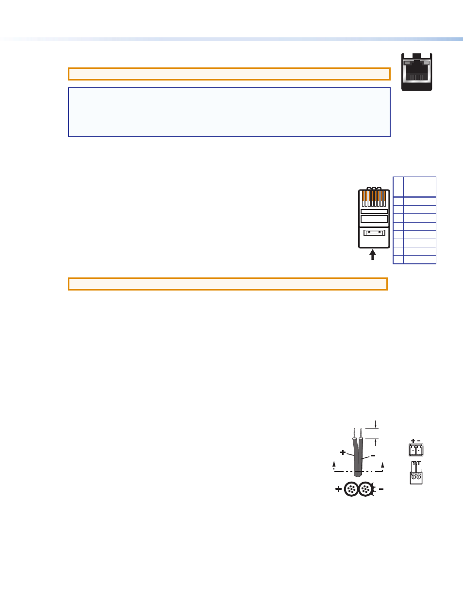
Step 4 — Run Cables Between Units
Connect the rear panel transmitter output to a rear panel receiver input using twisted pair cable.
Wire the cable as shown in the diagram to the right.
For optimal performance, Extron highly recommends the following:
z
RJ-45 termination with shielded twisted pair cable must comply with TIA/EIA-T568B wiring
standard for all connections.
For more information on TP cable wiring and termination, see the full product user guides at
z
Use shielded twisted pair cable, 24 AWG solid conductor or better, with a minimum cable
bandwidth of 400 MHz.
ATTENTION:
Do not use Extron UTP23SF-4 Enhanced Skew-Free AV UTP cable or STP201 cable.
z
Use shielded RJ-45 plugs to terminate the cable.
z
Limit the use of RJ-45 patches. Overall transmission distance capabilities vary depending on the number of patches
used. If possible, limit the number of patches to 2 total.
z
If RJ-45 patches must be used in the system, shielded patches are recommended.
Step 5 — Connect the Outputs from a Compatible Receiver
a.
DVI or HDMI output connector — Connect a DVI or HDMI cable (depending on your receiver type) between this port
and the input port of the display.
b.
Audio output — Connect a stereo audio device to this 3.5 mm mini stereo jack to receive the passed-through
unbalanced audio.
c.
RS-232/IR Pass-Through connector — Plug an RS-232 or modulated IR device into the RS-232/IR pass-through port.
Step 6 — Power the Units
The units can be powered one of two ways:
z
Locally with the included power supply. A compatible receiver can then be powered
remotely through the DTP line.
z
Remotely via the DTP line by a locally powered DTP 230 or 330 compatible device.
Wire the 2-pole captive screw connector for the included external 12 VDC power supply as
shown at right.
Step 7 — Final Installation
a.
Make all connections, power the units, and test the system for satisfactory operation.
b.
At the power outlet, unplug the power supply.
c.
Mount the transmitter into the wall box, and attach the supplied Decora faceplate to the unit.
d.
At the power outlet, reconnect the power supply. This powers up both units.
SECTION A–A
A
A
Power Supply
Output Cord
Captive Screw
Connector
Ridges
Smooth
3/16"
(5 mm) Max.
5
Pin
1
2
3
6
7
8
4
Wire color
White-green
Green
White-orange
White-blue
Orange
White-brown
Brown
Blue
TIA/EIA
T568B
TP Wires
12345678
Pins:
SIG LINK
DTP OUT
SIG LINK
DTP IN