Ea b c d, Step 3 — connect inputs to the transmitter, Front panel – Extron Electronics DTP T UWP 232_332 D Setup Guide User Manual
Page 2: Rear panel, Attention
2
DTP T HWP/UWP 232/332 D • Setup Guide (Continued)
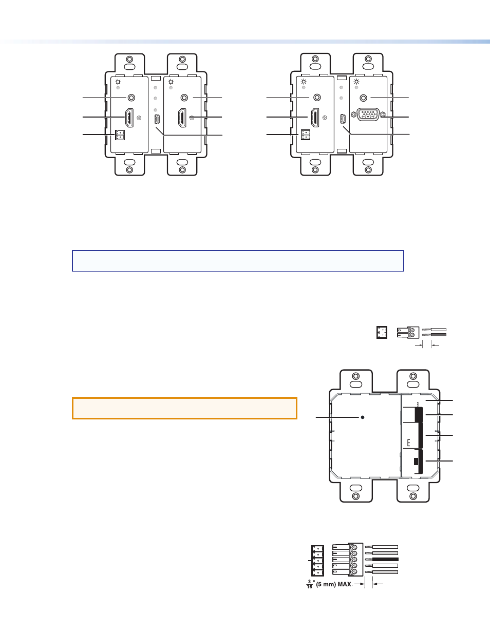
Step 3 — Connect Inputs to the Transmitter
Front Panel
A
Audio input connector — Connect an unbalanced stereo audio source to this 3.5 mm mini stereo jack.
NOTE:
The units do NOT embed analog audio onto the HDMI signal. This analog audio signal is
transmitted simultaneously with audio embedded within the HDMI signal.
B
HDMI input connector — Connect an HDMI cable between this port and the output port of the digital video source.
C
VGA input connector — Connect a VGA cable between this port and the output port of the video source.
D
IR output connector — Connect an IR device to this 2-pole, 3.5 mm captive screw pass-through connector for IR
control.
Wire the cable as shown in the illustration to the right.
E
Mini USB port — Connect a male Mini USB B cable to this port for SIS configuration and
firmware updates.
Rear Panel
A
DC power input connector — Wire and plug the included external
12 VDC power supply into either this 2-pole connector or the power
input connector on the receiver.
ATTENTION:
See Step 6 on the following page before wiring or
connecting the power supply.
B
Over DTP connector — Connect an RS-232 device to this 3-pole,
3.5 mm captive screw connector for pass-through RS-232 control.
C
Remote connector — Connect an RS-232 device, contact closure
device, or both to this 5-pole, 3.5 mm captive screw connector to
control switching on the unit. Wire the connector as shown in the
diagram to the right.
•
RS-232 — To control the unit through this port, connect an RS-232
device and configure it as follows: 9600 baud rate, 8 data bits,
1 stop bit, no parity.
•
Contact — Momentarily short pins 1 or 2 to ground (G) to select
the corresponding input. Connect pins 1
and 2 to ground (G) to
set the unit to auto switch mode. The device selects the highest
active input (auto switch).
AUTO SW
CONFIG
IR OUT
HDMI IN
AUDIO IN
S
G
HDCP
1
AUDIO IN
VGA IN
Extron
AUTO SW
CONFIG
IR OUT
HDMI IN
AUDIO IN
S
G
HDCP
1
2
HDMI IN
AUDIO IN
Extron
DTP T HWP 232/332 D
Front Panel
DTP T UWP 232/332 D
Front Panel
A
B
D
A
B
E
D
B
A
A
C
E
R
DTP OUT
REMO
TE
O
VER
DTP
SIG
LIN
K
RS-232
CONT
AC
T
Tx Rx
Tx Rx
G
PO
WE
R
12V
A MA
X
0.9
+–
G1
2
A/
S
R
DTP OUT
REMO
TE
O
VER
DTP
SIG
LIN
K
RS-23
2
CONT
AC
T
DTP
T UWP 232
D
Tx Rx
Tx Rx
G
PO
WE
R
12V
A MA
X
0.9
+–
G1
2
A/
S
DTP T HWP/UWP 232/332 D
Rear Panel
DTP T UWP 232 D
Rear Panel
1
2
5
6
3
E
A
B
C
D
Ground
Receive pin on connected unit
Transmit pin on connected unit
Connected RS-232 and
Contact Closure Device Pins
Tx/Rx
Pins
Pin 1 for contact closure control
Pin 2 for contact closure control
Rx
Tx
RS-232
Contact
2
1
G
3/16”
(5 mm) Max.
G
Ground
S
Signal