Extron Electronics DTP T UWP 232_332 D Setup Guide User Manual
Installation, Step 1 — disconnect power, Step 2 — prepare the mounting surface
IMPO
RTAN
T:
Go to ww
w.extr
on.com
for the complete
user guide
, installation instructions,
and
specifications bef
ore connecting the
product to the po
wer sour
ce.
DTP T HWP/UWP D 232/332 D • Setup Guide
This setup guide provides instructions for an experienced installer to set up and operate the
Extron DTP T HWP D and DTP T UWP D family of wallplate extenders.
Installation
Step 1 — Disconnect Power
Disconnect all equipment power sources.
Step 2 — Prepare the Mounting Surface
ATTENTION:
•
Installation and service must be performed by authorized
personnel only.
•
The installation shall be in accordance with applicable
provisions of the National Electrical Code and any local
electrical codes.
NOTE:
Use a wall box with a depth of at least 3.0 inches
(7.6 cm). Alternatively, the included mud ring (MR 200)
can be used. For more information, see the full product
user guide at
a.
Place the wall box against the installation surface and mark the
opening guidelines.
TIP:
Use a level to mark the opening.
b.
Cut out the material from the marked area.
c.
Secure the wall box to the wall stud with 10-penny nails or #8 or #10 screws, leaving the front edge flush with the
surface.
d.
Run all required cables (see steps 3, 4, and 5) and secure them with cable clamps.
TIP:
In order to fit the unit in the junction box, do not
install boots on TP cables and RJ-45 connectors.
Extron
DTP T UWP 232/332 D
Signal Output
Cable
Cable
Clamp
Decora Faceplate
Screws or
Nails
Wall opening is
flush with edge of box.
Wall Stud
AUT
O S
W
CONF
IG
IR
OU
T
HDM
I IN
AUDI
O I
N
G
S
HDCP
1
AUDI
O I
N
VGA
IN
AUTO SW
CONFIG
IR OUT
HDMI IN
AUDIO IN
S
G
HDCP
1
HDMI IN
AUDIO IN
HDCP
1
2
AUTO SW
CONFIG
IR OUT
HDMI IN
AUDIO IN
S
G
HDCP
1
AUDIO IN
VGA IN
TLP 1000TV
IPCP 505
IN1608
DTP HDMI 230 Rx
Projector
100-240V ~ -- A MAX
1
2
CONFIGURABLE
HDMI
HDMI
5
6
7
8
C
RS-232 IR
RS-232
IR
Tx Rx
Tx Rx
G
Tx Rx
Tx Rx
G
Tx Rx
Tx Rx
G
HDMI
A
B
3
4
INPUTS
OUTPUTS
Tx Rx
RS-232
G
LAN
2x25W(8Ω)/2x50W(4Ω)
RESET
AUDIO INPUTS
OUTPUTS
REMOTE
L
L
1
R
R
L 2
R
L
3
R
CLASS 2 WIRING
L
4
R
L
5
R
+48V
+48V
1
2
L
R
VARIABLE
IN1608 SA
2
MIC/LINE
L
6
R
SIG LINK
DTP IN
SIG LINK
DTP IN
SIG LINK
DTP OUT
50/60 Hz
RS-232
IR
OVER DTP
OVER DTP
OVER DTP
AMPLIFIED OUTPUT
VOLUME
SCALING PRESENTATION SWITCHER
IN1608
INPUTS
1
HDCP
SIGNAL
OUTPUTS
ENTER
MENU
Extron
2
3
4
5
6
7
8
A
B
C
INPUTS
1 2 3 4 5 6 7 8
CONFIG
Extron
DTP T UWP 232 D Tx
Transmitter
Extron
DTP T HWP 232 D Tx
Transmitter
Ethernet
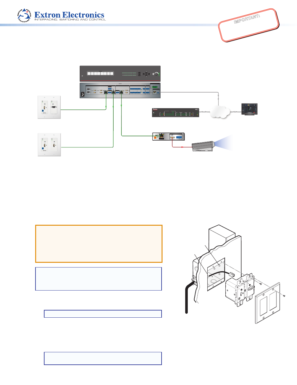
A Typical DTP T HWP 232 D and DTP T UWP 232 D Application
Network
L
R
POWER
12V
0.7A MAX
AUDIO
SIG LINK
DTP IN
OUTPUTS
XTP DTP 24 Cable
230 '
XTP DTP 24 Cable
230 '
XTP DTP 24 Cable
230 '
HDMI
1
2
3
4
5
6
7
8
100
LINK
ACT
COM
IR/S
TX
RX
TX
RX
RTS
CTS
R
5
1
6
2
7
3
8
4
RELAY
FLEX
I/O
5
1
6
2
3
1
4
2
eBUS
ACT LIMIT
OVER
SWITCHED
12VDC
3
1
4
OVER
2 LIMIT
IR
7
3
8
4
IPCP 505