Front panel, Front.panel – Extron Electronics FOX Matrix 14400 Setup Guide User Manual
Page 9
Front Panel
FOX MATRIX 320x
FIBER OPTIC DIGITAL MATRIX SWITCHER
PRIMARY
1
POWER SUPPLY
REDUNDANT
1
PRIMARY
2
REDUNDANT
2
STATUS
CONFIG
7
8
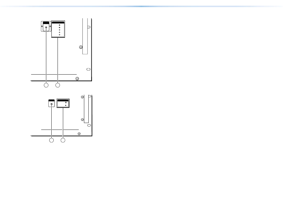
Figure 6.
Front Panel Configuration Port, FOX Matrix 320x
FOX MATRIX 14400
CONFIG
FIBER OPTIC DIGITAL MATRIX SWITCHER
POWER SUPPLY
PRIMARY
REDUNDANT
7
8
Figure 7.
Front Panel Configuration Port, FOX Matrix 1400
g
Configuration port — If desired, connect a control system or
computer to the front panel Configuration (RS-232) port. Use
an optional 9-pin D to 2.5 mm mini jack TRS RS-232 cable,
part #70-335-01.
h
Status LEDs —
Primary and Redundant Power Supply LEDs —
Green — Indicates that the associated power supply is
operating within normal tolerances.
Amber (FOX Matrix 320x only) — Indicates that AC power is
disconnected or the power supply has been removed.
Red — Indicates that the associated power supply is operating
outside the normal tolerances or has failed. See
Status LED (FOX Matrix 320x only) —
Green — Indicates that the controller board is operating
normally and that the temperature and backplane voltages are
all within normal tolerances.
Red — Indicates that either the controller board has failed
or that temperature or backplane voltages are outside of
acceptable levels.
Figure 8.
Front Panel Configuration Port, FOX Matrix 320x
g
Configuration port (FOX Matrix 320x) — If desired, connect a control
system or computer to the front panel Configuration port, a mini USB
B port.
10
FOX Matrix 320x and FOX Matrix 14400 • Installation
11
FOX Matrix 320x and FOX Matrix 14400 • Installation