Removing and installing a power supply module, Removing.and.installing. a.power.supply.module, Maintenance and modifications – Extron Electronics FOX Matrix 14400 Setup Guide User Manual
Page 19: Maintenance, And modifications, Removing.and.installing.a.power.supply.module
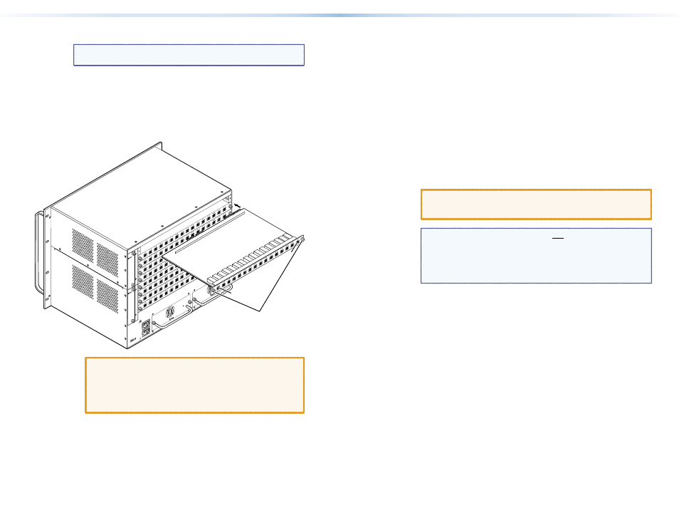
Remove and replace an I/O board or blank panel as follows:
NOTE: The I/O boards are hot-swappable. You do not need to
power down the switcher to remove an I/O board.
1.
For an I/O board, disconnect any connected cables.
2.
Rotate the left and right knurled knobs to completely loosen the
captive screws.
3.
Gently pull on the knurled knobs/captive screws to loosen the
board or panel from the backplane.
4.
Slide the board or panel out of the chassis (below).
ANAHEIM, CA
RESET
RS232/RS422
REMOTE
LAN
ACT
LINK
100-240V
50/60Hz
1.2A MAX.
100-240V
50/60Hz
1.2A MAX.
REDUNDANT
PRIMAR
Y
PRIMAR
Y POWER SUPPL
Y
DISCONNECT BOTH POWE
R
CO
RD
S B
EF
OR
E S
ER
VIC
ING
REDUNDANT POWER SUPPL
Y
A
B
C
D
E
F
G
H
I
J
K
L
M
N
O
P
OU
T
IN
OU
T
IN
OU
T
IN
OU
T
IN
OU
T
IN
OU
T
IN
OU
T
IN
OU
T
IN
OUT
IN
OU
T
IN
OUT
IN
OUT
IN
OUT
IN
OU
T
IN
OUT
IN
OUT
IN
A
B
C
D
E
F
G
H
I
J
K
L
M
N
O
P
OU
T
IN
OU
T
IN
OU
T
IN
OU
T
IN
OU
T
IN
OU
T
IN
OU
T
IN
OU
T
IN
OU
T
IN
OU
T
IN
OUT
IN
OU
T
IN
OUT
IN
OUT
IN
OU
T
IN
OU
T
IN
A
B
C
D
E
F
G
H
I
J
K
L
M
N
O
P
OU
T
IN
OU
T
IN
OU
T
IN
OU
T
IN
OU
T
IN
OU
T
IN
OU
T
IN
OU
T
IN
OU
T
IN
OU
T
IN
OUT
IN
OUT
IN
OUT
IN
OUT
IN
OUT
IN
OUT
IN
A
B
C
D
E
F
G
H
I
J
K
L
M
N
O
P
OU
T
IN
OU
T
IN
OU
T
IN
OUT
IN
OU
T
IN
OU
T
IN
OU
T
IN
OU
T
IN
OU
T
IN
OU
T
IN
OUT
IN
OUT
IN
OU
T
IN
OU
T
IN
OUT
IN
OUT
IN
A
B
C
D
E
F
G
H
I
J
K
L
M
N
O
P
OU
T
IN
OU
T
IN
OU
T
IN
OUT
IN
OU
T
IN
OU
T
IN
OU
T
IN
OU
T
IN
OUT
IN
OU
T
IN
OU
T
IN
OUT
IN
OU
T
IN
OU
T
IN
OUT
IN
OUT
IN
A
B
C
D
E
F
G
H
I
J
K
L
M
N
O
P
OU
T
IN
OU
T
IN
OU
T
IN
OU
T
IN
OU
T
IN
OU
T
IN
OU
T
IN
OUT
IN
OU
T
IN
OU
T
IN
OUT
IN
OUT
IN
OU
T
IN
OU
T
IN
OUT
IN
OUT
IN
A
B
C
D
E
F
G
H
I
J
K
L
M
N
O
P
OU
T
IN
OU
T
IN
OU
T
IN
OU
T
IN
OU
T
IN
OU
T
IN
OU
T
IN
OU
T
IN
OUT
IN
OU
T
IN
OUT
IN
OU
T
IN
OUT
IN
OU
T
IN
OUT
IN
OUT
IN
A
B
C
D
E
F
G
H
I
J
K
L
M
N
O
P
OU
T
IN
OU
T
IN
OU
T
IN
OUT
IN
OU
T
IN
OU
T
IN
OU
T
IN
OU
T
IN
OU
T
IN
OU
T
IN
OUT
IN
OU
T
IN
OUT
IN
OU
T
IN
OU
T
IN
OUT
IN
1 - 16
17 - 32
33 - 48
49 - 64
65 - 80
81 - 96
97 - 112
113 - 128
129 - 144
FAN ASSIMBL
Y
FAN ASSIMBL
Y
Align with
Plastic Guides
IN
A
B
C
D
E
F
G
H
I
J
K
L
M
N
O
P
OU
T
IN
OUT
IN
OU
T
IN
OUT
IN
OU
T
IN
OUT
IN
OUT
IN
OU
T
IN
OUT
IN
OUT
IN
OUT
IN
OU
T
IN
OUT
IN
OU
T
IN
OU
T
IN
OU
T
IN
Knurled
Knobs
A
P
CAUTION:
Do not touch the electronic components or the
connectors on the backplane or on the circuit
boards without being electrically grounded.
Handle circuit boards by their edges only.
Electrostatic discharge can damage circuits, even
if you cannot feel, see, or hear it.
5.
Place the removed board on an anti-static surface or in an anti-
static container.
6.
For an I/O board, orient the board to be installed so that
transceiver module A (fiber board) is on the left and transceiver
module P is on the right.
7.
For an I/O board, align the board with the left and right chassis
guides (above).
8.
Gently slide the board or blank panel into the enclosure. For an
I/O board, slide the board toward the front panel until it meets
resistance.
9.
Gently seat the board or panel in the backplane.
10.
Use a screwdriver to tighten the left and right knurled knobs/
captive screws to lock the board or panel in place.
Removing and Installing a Power Supply Module
The FOX Matrix 14400 has two power supply modules and the
FOX Matrix 320x has four power supply modules. The modules for
each model are identical and hot-swappable. Each power supply
module has a 2-color LED, visible on the rear panel, that indicates the
status of the power supply outputs. If the LED is lit green, the power
supply is operating normally. If the LED is lit red, the supply has
failed and should be replaced at the earliest opportunity. LEDs with
identical meaning are also on the front panel.
CAUTION:
The FOX matrix switchers use double pole/neutral
fusing. Power must be disconnected before servicing
internal components.
NOTES: • Power supply modules are not interchangeable
between models.
• The power supply modules are hot-swappable. Either
power supply can be removed without powering down
the switcher. You do not need to power down the
switcher to install a power supply module.
1.
Rotate the left and right knurled knobs to completely loosen the
captive screws.
2.
Gently pull on the handle to loosen the power supply from the
backplane.
3.
Slide the power supply out of the chassis.
4.
Orient the power supply module to be installed with the LED up
(FOX Matrix 320x) or to the right (FOX Matrix 14400).
5.
Align the flanges on the power supply module with the left and
right power supply guides (see the next page).
6.
Gently slide the power supply module into the enclosure until the
power supply meets resistance.
7.
Gently seat the power supply in the backplane.
8.
Use a screwdriver to tighten the left and right knurled knobs/
captive screws to lock the power supply in place.
26
FOX Matrix 320x and FOX Matrix 14400 • Maintenance and Modifications
27
FOX Matrix 320x and FOX Matrix 14400 • Maintenance and Modifications