Installation, Rear panel, A note on i/o boards – Extron Electronics FOX Matrix 14400 Setup Guide User Manual
Page 6: Rear.panel, A.note.on.i/o.boards
Installation
This.section.describes.installation.of.the.FOX.matrix.switchers,.
including.connections.and.features..Topics.that.are.covered.include:
•
•
Front.Panel
Rear Panel
A Note on I/O Boards
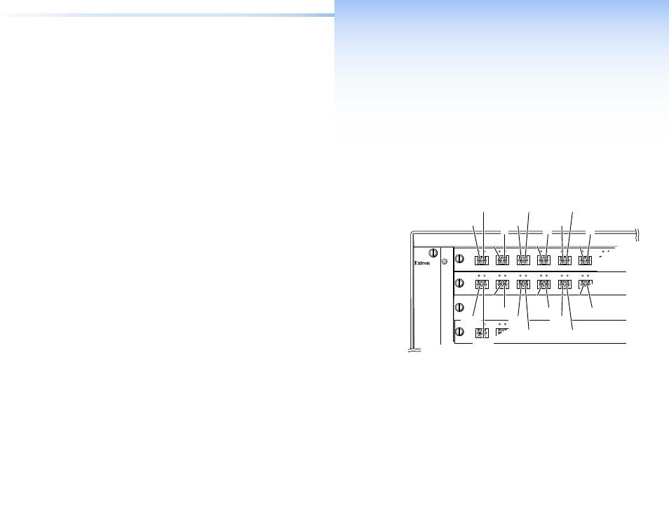
As.shown.in.figure.2,.each.I/O.board.is.identified.by.the.input.and.
output.numbers.supported.by.the.board.position..The.transceiver.
modules.on.the.boards.are.identified.as.A.through.P.
A
B
C
D
E
F
OUT
IN
OUT
IN
OUT
IN
OUT
IN
OUT
IN
OUT
IN
OUT
IN
OUT
IN
IN
OUT
A
B
C
D
E
OUT
IN
OUT
IN
OUT
IN
OUT
IN
OUT
IN
OUT
IN
1 - 16
17 - 32
33 - 48
49 - 64
FAN ASSEMBLY
Slot 1
Inputs 1-16
Outputs 1-16
Output
1
Input
1
Slot 2
Inputs 17-32
Outputs 17-32
Slot 3
No board
installed
Slot 4
Inputs 49-64
Outputs 49-64
Output
3
Input
3
Output
2
Input
2
Output
5
Input
5
Input
19
Input
21
Output
4
Input
4
Output
6
Output
18
Output
20
Output
22
Input
6
Input
18
Input
22
Output
17
Output
19
Input
17
Output
21
Input
20
Figure 2.
Arrangement of Inputs and Outputs on the I/O Boards
The.board.position.designators.correspond.to.the.input.and.output.
numbers.served.by.that.position.(1.-.16,.17.-.32,.and.so.on).
The.location.designators,.A.through.P,.correspond.to.the.transceiver.
modules,.numbered.from.left.to.right,.each.of.which.includes.an.
input.and.an.output.
See.figure.2..The.input.and.output.numbers.supported.by.the.
I/O.board.in.location.17.-.32.are.as.follows:.A.=.17,.B.=.18,.C.=.19,.
D.=.20,.and.so.on.
4
FOX Matrix 320x and FOX Matrix 14400 • Introduction
5
FOX Matrix 320x and FOX Matrix 14400 • Installation