Making connections, Making connections -4, Connect the hardware – Extron Electronics FOX 4G Matrix 7200 Setup Guide User Manual
Page 9: Installation, cont’d
Refer also to the FOX 4G Matrix Switchers User’s Manual at www.extron.com.
Refer also to the FOX 4G Matrix Switchers User’s Manual at www.extron.com.
Making connections
a
Fiber optic connectors and LEDs —
W
This unit outputs continuous invisible light, which
may be harmful and dangerous to the eyes; use with
caution. For additional safety, plug the attached dust
caps into the optical transceivers when the fiber optic
cable is unplugged.
N
Ensure that you use the proper fiber cable for your I/O
board. Typically, singlemode fiber has a yellow jacket and
multimode cable has an orange jacket.
N
The FOX 4G Matrix Switchers use one connector on the
block as an input and the second connector on the same
block as a separate output.
Ä
Input connector —
Connect a fiber optic
cable between each Input
LC connector and a
FOX 500 Tx or any other
compatible Extron FOX
device.
N
Or, for the serial return (receiver-
to-transmitter) function, connect
the far end to the Optical 2
connector on a FOX Rx receiver.
Input LED —
When lit,
the link is active (light is
received).
Å
Output connector —
Connect a fiber optic cable
between each output
LC connector and a FOX 500 Rx
or any other compatible Extron
FOX device.
N
Or, for the serial return
(receiver-to-transmitter)
function, connect the far end
to the Optical 2 connector on a
FOX Tx transmitter.
Output LED —
This LED is
always lit.
OUT
IN
OPTICAL
2* 1
*
OPTIONAL FOR
RETURN DATA
LINK
LINK
OPTICAL
FOX 500 Tx
Transmitter
FOX 500 Rx
Receiver
FOX 4G Matrix
Switcher
1 2*
*
OPTIONAL FOR
RETURN DATA
LINK
LINK
1b
1a
b
SDI/HDI-SDI BNC connectors —
Ç
Multi-rate SDI Input connectors — Connect HD-SDI, SDI,
or 3G-SDI video inputs to these BNC connectors.
É
Multi-rate SDI Output connectors — Connect digital
displays to these BNC connectors.
c
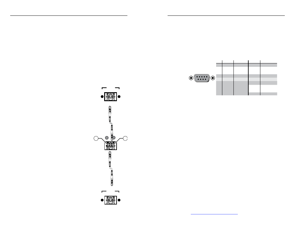
Remote port — If desired, connect a control system or computer
to the rear panel Remote RS-232/RS-422 port.
RS-232 Function
Pin
Function
1
2
3
4
5
6
7
8
9
—
TX
RX
—
Gnd
—
—
—
—
Not used
Transmit
Receive
Not used
Ground
Not used
Not used
Not used
Not used
—
TX–
RX–
—
Gnd
—
RX+
TX+
—
Not used
Transmit (–)
Receive (–)
Not used
Ground
Not used
Receive (+)
Transmit (+)
Not used
RS-422
5
1
9
6
Figure 2-6 —
Audio output connector wiring
d
Ethernet port — If desired, connect a network WAN or LAN
hub, a control system, or a computer to the Ethernet RJ-45 port.
Network connection
— Wire as a patch (straight) cable.
Computer or control system connection
— Wire the interface
cable as a crossover cable.
N
The factory default IP address is 192.168.254.254.
e
Switch Reference connectors (affect SDI / HD-SDI inputs and
outputs only) —
Connect an external sync signal to this BNC
connector to genlock the video signal in broadcast or other sync-
critical applications.
f
Power connectors — Plug the switcher into two grounded AC
sources.
N
For reliability, connect the Redundant power cord to either
an uninterruptible power source or to a power source that
is completely independent from the primary power source.
g
Primary and Redundant power supply indicator LEDs —
Green —
Indicates that the associated power supply is
operating within normal tolerances.
Red —
Indicates that the associated power supply is operating
outside the normal tolerances or has failed. See chapter 5,
“Maintenance and Modifications“ to replace the power supply.
FOX 4G Matrix Switchers • Installation
Installation, cont’d
2-4
FOX 4G Matrix Switchers • Installation
2-5