Extron Electronics EDID 101H User Guide User Manual
Page 13
EDID 101H • Installation
7
d
EDID Store LED – One bi-color LED lights green when power is connected. It flashes
amber when reading and storing EDID from a connected output device, returning to
green when recording is complete.
e
EDID Store button – One recessed push button initiates both reading and storing
EDID. With both A and B DIP switches set off (down), press the store button to read
the EDID of a device connected to the output. The EDID is then stored to a user slot
selected by the rotary switch. Up to 15 EDID files can be stored.
Reset
–
To reset the EDID 101H to its default state, press and hold the EDID button
while applying power. As power is applied, all front panel LEDs blink three times
indicating a successful reset.
f
EDID selection rotary wwitch – One 16-position rotary switch combined with
DIP switches A and B (see figure 4, g on page 5) provide a choice of user stored or
pre-programmed EDID (see
User Loaded EDID – With both DIP switches off (down) rotary positions 1 through F
store user loaded EDIDs (see
memory slot is selected before initiating the EDID read and store.
Automatic EDID – With both DIP switches off (down) and the rotory switch at
position 0, the EDID of a device connected to the output is automatically stored upon
detection of HPD. If no device is detected, the default EDID (720p60) is loaded.
g
DIP switch A and B – Two 2-position DIP switches, A and B, are used with the rotary
switch to select from pre-programmed HDMI and DVI EDID, or to allow recording a
custom EDID from a connected display. The “off” position is down.
h
DIP Switch C – DIP switch C enables (default: up) or disables (down) HDCP
authorization.
i
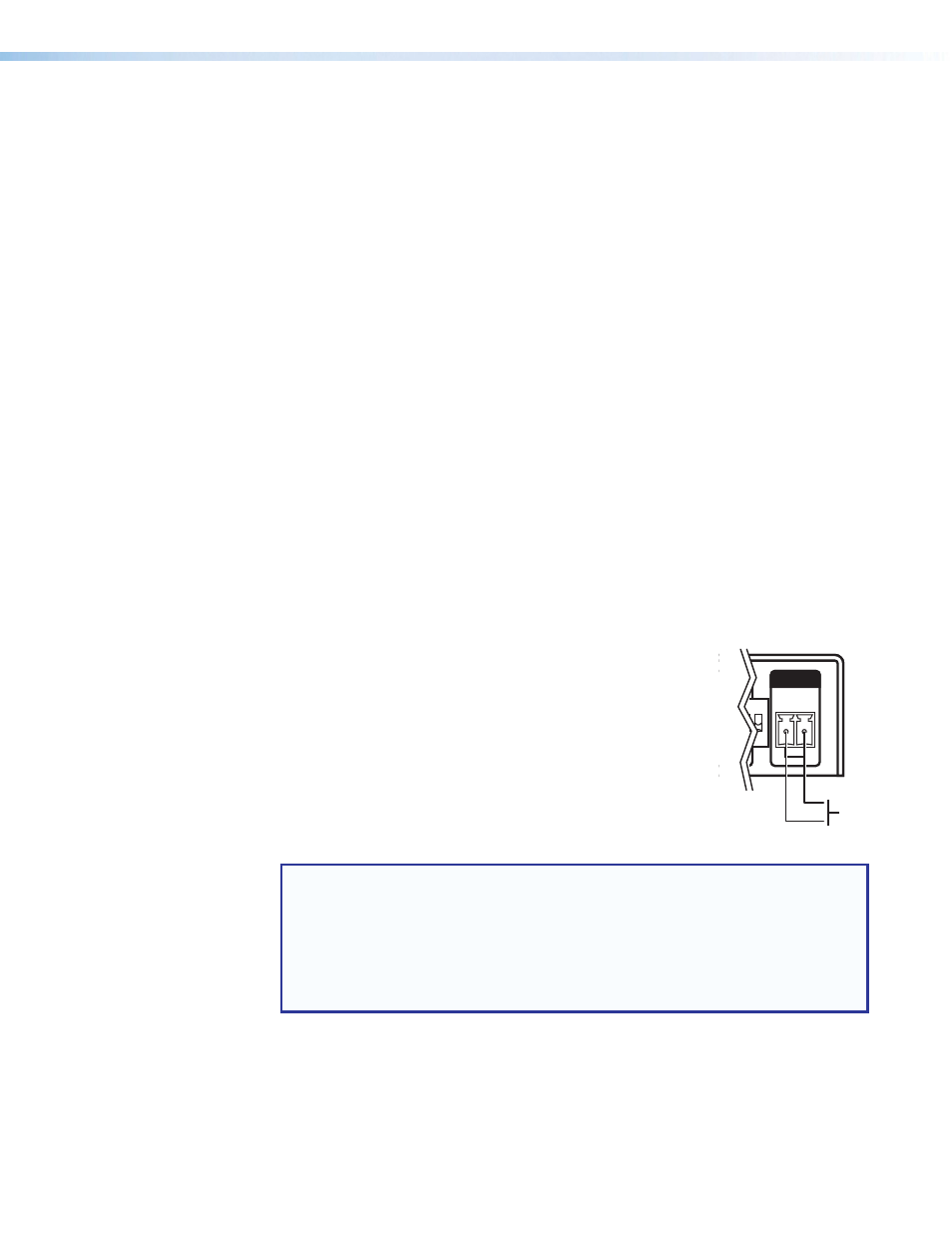
Hot Plug Detect (HPD) – One 2-pole 3.5 mm captive screw
connector used to manually toggle HPD on the HDMI input.
When the two pins (A and B) are shorted together, an HPD event
is initiated on the HDMI input.
POWER
12V
- - A MAX
EDID
STORE
A B
A B
C
OUTPUT
INPUT
EDID
HPD
0
1
2
3 4 5 6 7
8
9
A
B
C
D
E
F
ON
1 2 3
Momentary
Push
Button
NOTES:
•
The length of the exposed wires in the stripping process is critical. The ideal
length is 3/16 inch (5 mm). If it is any longer, the exposed wires may touch,
causing a short circuit between them. If it is any shorter, the wires can be easily
pulled out even if tightly fastened by the captive screws.
•
Do not tin the wires. Tinned wire does not hold its shape and can become
loose over time.