Application diagram, Touchlink, Control system – Extron Electronics DP DA2 User Guide User Manual
Page 8: Tcp/ip, Extron dp da2 displayport distribution amplifier, Figure 1. typical dp da2 application
HDCP visual confirmation — Provides a green signal when encrypted content is sent to
a non-compliant display. A full-screen green signal is sent when HDCP-encrypted content
is transmitted to a non-HDCP compliant display, providing immediate visual confirmation
that protected content cannot be viewed on the display.
Key Minder
®
— Authenticates and maintains continuous HDCP encryption between all
input and output devices to enable simultaneous distribution of a single source signal to
two or more displays.
Automatic input cable equalization — Up to 25 feet (7.6 meters) at 2560x1600 @ 60
Hz with Extron DisplayPort cables. Conditions incoming digital signals to compensate for
signal loss from long cables, low quality cables, or source devices with poor DisplayPort
signal output.
LED indicators — Provide real-time feedback and monitoring of key performance
parameters by indicating signal presence and HDCP authentication. The tri-color EDID
LED indicator on the back panel shows whether an internal or external EDID is stored.
RS-232 serial control — Allows control by SIS
™
commands either via the controller or
directly from a PC using the front panel USB port or the rear panel 3-pole captive screw
connector.
Output muting control via RS-232 or contact closure — Provides the capability to
mute one or both outputs at any time. This allows content to be viewed on a local monitor
prior to appearing on the main presentation display.
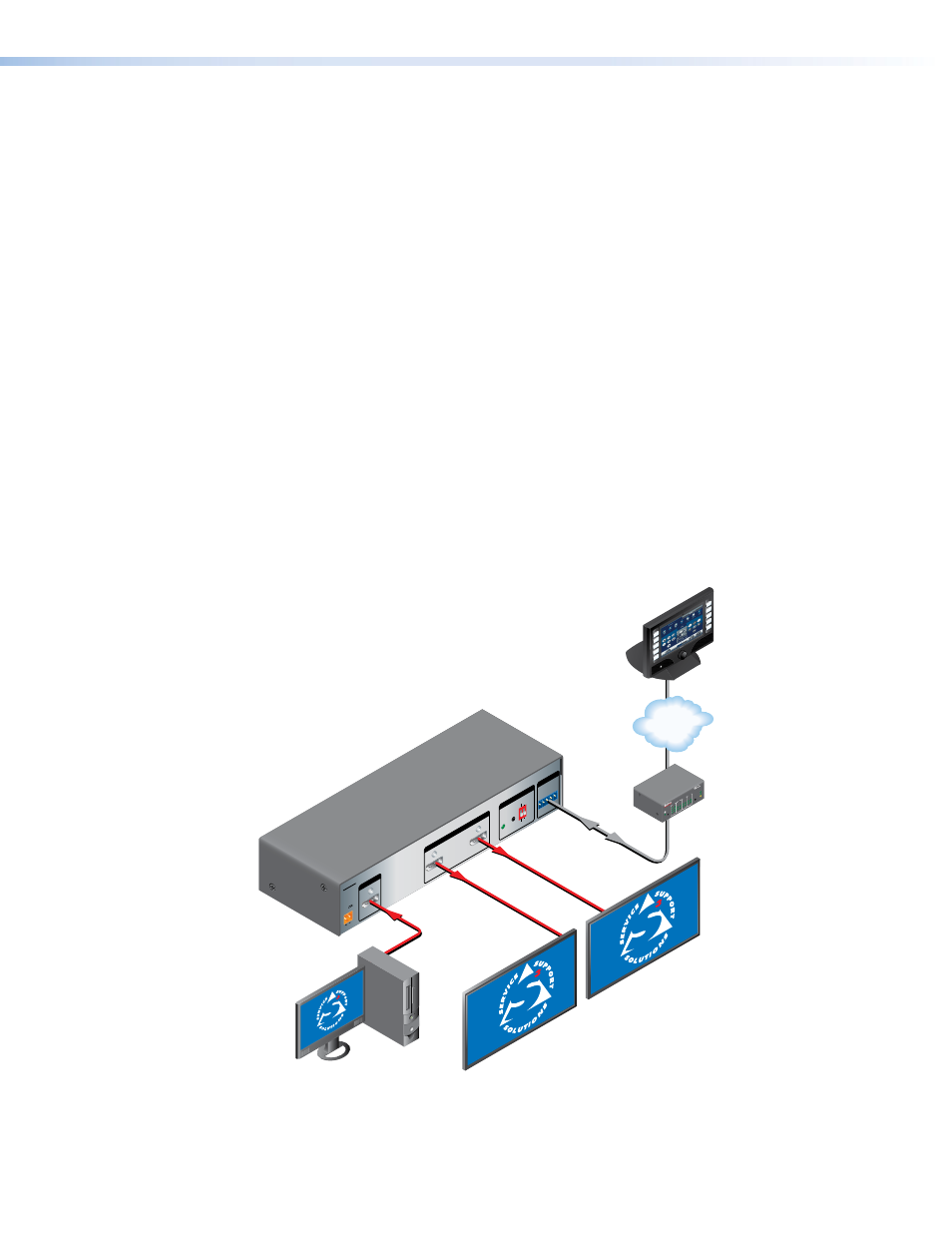
Application Diagram
12V
0.6A MA
X
POWE
R
EDID
STORE
EXTEND
NORMAL
DE
FA
UL
T
STORE
D
1
RS-232
MUTE
Rx
Tx
1
G
2
2
INPU
T
REMOTE
EDID
OUTPUTS
DP DA
2
Flat Panel Displays
with DisplayPort Inputs
Extron
DP DA2
DisplayPort
Distribution
Amplifier
PC with DisplayPort Output
1
3
1
4
2
3
1
4
2
3
1
4
2
2
3
100
LIN
K
AC
T
CO
M
IR
INP
UT
RE
LA
Y
TX
RX
R
IPL 25
0
®
ON
OF
F
DIS
PLA
Y
MU
TE
SC
RE
EN
UP
SC
RE
EN
DO
WN
VC
R
DV
D
DO
C
CA
M
LAP
TO
P
PC
TCP/IP
TouchLink
Control
System
Figure 1.
Typical DP DA2 Application
DP DA2 • Introduction
2