Rcm modules, Installation and operation, cont’d, Config ir – Extron Electronics Control Modules User Manual
Page 8
Control Modules • Installation and Operation
Installation and Operation, cont’d
2-6
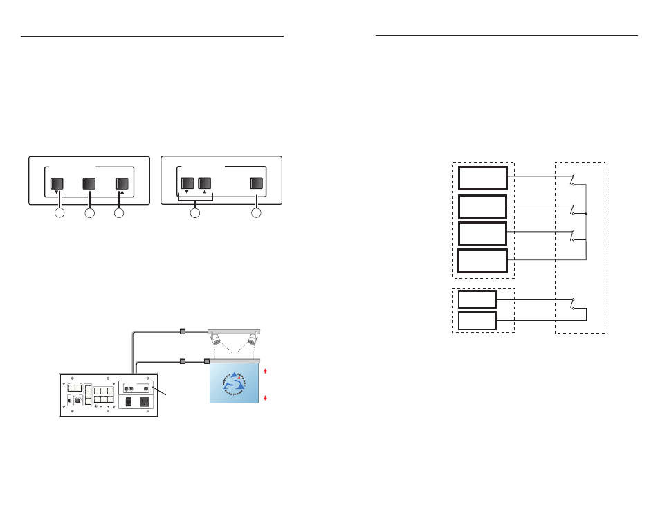
RCM modules
a
Screen Position Up/Down buttons — These buttons can be set
up to toggle the screen to move up or down.
b
Screen Position Stop button — Press this button to stop the
up/down motion of the screen.
c
Lighting On/Off button — This button acts like a light switch,
toggling the room lights on or off when pressed. This button
must be set up before it can control the lights.
SCREEN POSITION
DOWN
UP
STOP
2
1
1
ROOM CONTROL
SCREEN POSITION
LIGHTING
ON / OFF
1
3
RCM-SC LT
Front
RCM-SC
Front
Figure 2-5 — RCM modules front panel layout
N
Many different brands and models of low voltage
controllers can be used with the RCM modules to
control screen movement. An application example is
shown below. Different models require different wiring.
MLC 226 IP AAP
Low Voltage
Controller
AC Power
Controller
Extron
PROJECTOR
1
2
3
4
5
6
VOLUME
CONFIG
IR
ON
OFF
AUTO
IMAGE
MUTE
LAPTOP
VCR
DVD
AUX
VIDEO
PC
MLC 226 IP AAP
RCM-SC LT
UNSWITCHED
100-240V - 5AMAX
ROOM CONTROL
SCREEN POSITION
LIGHTING
ON / OFF
Figure 2-6 — Typical RCM application
2-7
Control Modules • Installation and Operation
N
The diagrams included here are examples only. Your
equipment may have different wiring requirements.
Refer to the specific wiring instructions provided by the
manufacturer of the screen or power controller that you
are using.
For screen controllers that require momentary closure between
the up, down, and common terminals to stop the screen in its
current position (e.g Da Lite and Draper), use the included
diodes (1N4001 or equivalent) between the up and common
(1 & 3) and down and common (2 & 3) terminals for reverse
bias protection.
C
2
1
C
3
C
Relay
Ports
Low Voltage
Controller
Up
Down
Stop
Red
(Da Lite/Draper)
Up (Stewart)
Stop (Stewart)
Black
(Da Lite/Draper)
Down (Stewart)
White (Da Lite)
Blue (Draper)
Common
(Stewart)
4
C
AC Power
Controller
12VDC
Common
Figure 2-7 — MLC/System 5 IP relay wiring block
diagram for an RCM-SC LT