Ul requirements, Installation overview, Installation and operation – Extron Electronics Control Modules User Manual
Page 6
Control Modules • Installation and Operation
Installation and Operation
2-2
UL Requirements
•. These units are not to be connected to a centralized DC power
source or used beyond their rated voltage range.
• These units must be installed in UL listed junction boxes.
N
The UL approved electrical wall box is not included
with the control module; the installer is responsible for
obtaining and installing the box.
• These units must be installed in accordance with the National
Electrical Code and with local electrical codes.
Installation Overview
For installation and set up, refer to the relevant diagrams and
sections in your MLC, System 5 IP or SCP user's manual:
1
.
Attach the control module to an AAP wall plate or an
Extron faceplate.
A
D
B C
E
A
D
B C
E
ON
1
2
1
1
2
The same type and quantity of rear panel connectors and
DIP switches shown above can be found on all models of
the control modules.
2
.
Using the rear panel connectors (
a
), connect control
modules together and to the MLC, System 5 IP or SCP
unit (see Figure 2-2). Follow the wiring diagrams in the
installation section of the user's manual of your MLC,
System 5 IP, or SCP unit.
N
Up to a total of four control module addresses in any
combination of models can be daisy-chained together
and connected.
N
After connecting the control modules, you must turn
the power to the MLC 206 off, then on for the device to
recognize the module quantity and types.
N
Extron recommends that you connect the cable’s drain
wire to the ground pin at both ends to reduce EMI
interference.
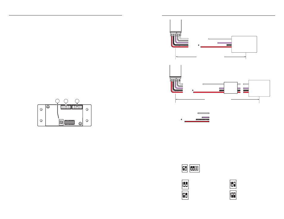
Figure 2-1 — Typical module Rear panel layout
C
Installation and service must be performed by
authorized personnel only. These products should
be used with UL approved electrical boxes.
Control Modules • Installation and Operation
2-3
E
D
C
B
A
SCP communication (IR)
Modulated IR (for IR Link)
Ground ( ) & drain wire
Control Module communication
+12 VDC
CTLP Cable Color Code:
= White
= Black and Drain
= Violet
= Red
System
Switcher
A B C D E
+12V OUT
GR
OUND
CONT MOD
IR IN
SCP COM
E
D
C
B
SCP Communication
Modulated IR
Control Module Communication
A +12 VDC
200' (61 m) max. Cable Length
(using Extron Comm-Link Cable )
SCP
B
A
C
E
Not all wires need to be connected (accessory dependent).
Control
Module
Maximum =
4 Control Module
Addresses
Ground ( ) (connect drain wire, both devices)
System Switcher, SCP and Control Module wiring
A B C D E
+12V OUT
GR
OUND
CONT MOD
IR IN
SCP COM
E
D
C
B
SCP Communication
Modulated IR
Ground ( ) (connect drain wire, both devices)
Control Module Communication
A +12 VDC
200' (61 m) max. Cable Length
(using Extron Comm-Link Cable)
Control
Module
Maximum =
4 Control Module
Addresses
Not all wires to and from the Control Module
are necessary (accessory dependent).
MLC and Control Module wiring
MLC
3
.
Connect an IR Emitter or IR Broadcaster to the MLC or
System 5 IP's IR output port (i.e., projector control port,
IR/Serial Port or Display/Source), maximum four emitters
(one per module address).
4
.
Set the DIP switches (
b
) on each control module’s
circuit board to identify the address of each module (see
illustrations below). Each module must have a unique
address. Note the direction of the arrow on the switch.
ON
1 2 3 4
ON
1 2
Address DIP switches can be 4-position or
2-position, but only positions 1 and 2 are used.
1, 2 — Control module address identification
ON
1 2
ON
1 2
1 and 2 down (off) =
address 0, control module
#1
1 up (on), 2 down (off) =
address 1, control module
#2
ON
1 2
ON
1 2
1 down (off), 2 up (on) =
address 2, control module
#3
1 up (on), 2 up (on) =
address 3, control module
#4
3, 4 — Not used
Figure 2-2 — Typical Control Module wiring