Cc 100c • installation guide (continued), Rear panel connections – Extron Electronics CC 100C User Manual
Page 2
CC 100C • Installation Guide (Continued)
2
Rear Panel Connections
V
N/A
LAN/PoE
0 1 G NO C NC
POWER IN
12-15V
12W MAX
MIC SPKR
INPUT RELAY
Rear Panel
10
14
15
13
12
9
8
11
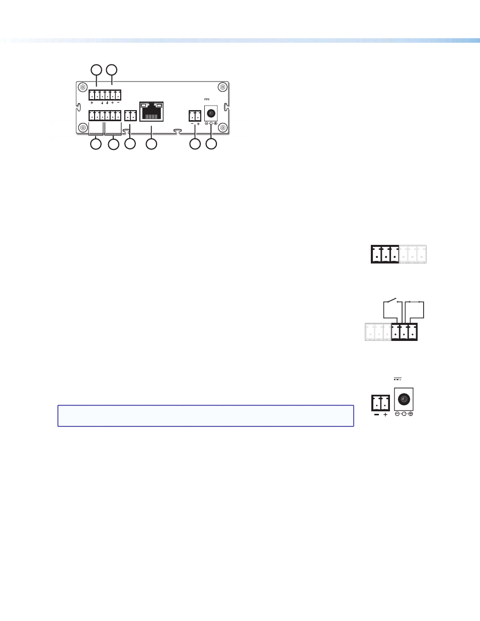
Rear panel connectors as shown in figure 3 are listed below.
h
Mic Input — Microphone audio input is carried on this 3-pole connection. Input is encoded and streamed over the
network. See "Cabling the CC 100C" section on page 3 for wiring details.
i
Speaker output (2 watt, mono) — For speaker output, connect a mono speaker to this 2-pole captive screw connector.
See "Cabling the CC 100C" section on page 3 for wiring details.
j
Configurable Input: Contact — Connect to this 3-pole captive screw connection
for contact input. When triggered the contact input initiates audio encoding for streaming
over the network. Connect port 0 or 1 to ground (G) to trigger the port.
k
Configurable Input: Relay — Connect to this 3-pole captive screw connection for relay
input. The connector has a normally open relay (NO), a common (C), and a normally closed
relay (NC).
l
N/A — This port is not used.
m
LAN/PoE — For networking use, connect the LAN to this RJ-45 connector. This port
supports Power over Ethernet standard up to 48 V. The two associated LEDs indicate
connection and data activity.
An optional PS PoE power injector (part number
70-828-01) can be used.
n
or
o
Power In — Connect a power supply to either the 2-pole captive screw connector or
to the coaxial connector for 12 V to 15 V power input. Observe the correct polarity.
NOTE:
It is recommended to use Extron power supplies, such as the 12 V, 1 A PS 1210 C
(part number
70-775-01) or the 15 V, 0.8 A PS 1508 C (part number 70-776-01).
0 1 G NO C NC
INPUT RELAY
NO C NC
RELAY
0 1 G NO C NC
INPUT RELAY
0 1 G
INPUT
Normally
Closed
Normally
Open
RELAY
Figure 3.
Rear Panel Connectors
POWER IN
12-15V
12W MAX